Double-frequency antenna

A dual-frequency antenna and antenna technology, which is applied to antennas, antenna coupling, antenna grounding devices, etc., can solve problems such as low elevation gain, and achieve the effects of low elevation gain and good axial ratio bandwidth.

Active Publication Date: 2011-07-06
SHENZHEN SATLEAD TECH CO LTD
View PDF4 Cites 29 Cited by
  • Summary
  • Abstract
  • Description
  • Claims
  • Application Information

AI Technical Summary

Problems solved by technology

[0009] 4. Low

Method used


Image

  • Double-frequency antenna
  • Double-frequency antenna
  • Double-frequency antenna

Examples


Embodiment Construction

[0031] The technical solution of the present invention will be further described below in conjunction with the drawings and specific embodiments of the specification.

[0032] It should be understood that the specific embodiments described herein are only used to explain the present invention, but not to limit the present invention.

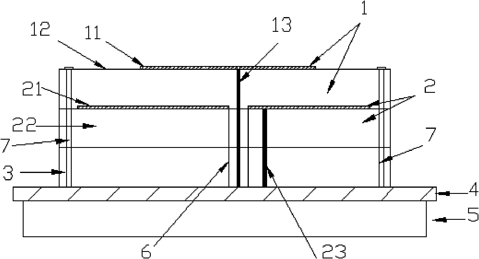
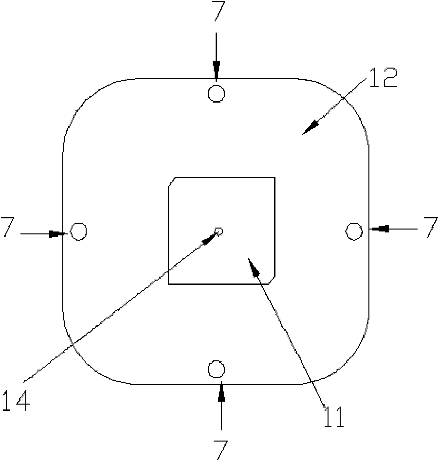
[0033] Such as figure 1 Shown is a schematic cross-sectional view of a preferred embodiment of the antenna of the present invention; this embodiment includes an upper microstrip antenna 1, a lower microstrip antenna 2, a dielectric layer 3, a reflector 4 and a shielding box 5; in the figure, 11 is The radiation patch of the upper microstrip antenna 1, 12 is the dielectric substrate of the upper microstrip antenna 1, and 13 is the feed pin of the upper microstrip antenna 1, wherein the center of the radiation patch 11 does not coincide with the center of the dielectric substrate 12 , That is, the center of the radiation patch 11 is deviated from the ce...


PUM


Abstract

The invention relates to an antenna which comprises an upper-layer microstrip antenna, a lower-layer microstrip antenna and a baffle board, wherein the upper-layer microstrip antenna and the lower-layer microstrip antenna are overlapped and then fixed on the baffle board through screws. The double-frequency antenna provided by the invention is easy to realize and has small volume, favorable axial ratio bandwidth and low elevation gain.

Description

Technical field [0001] The invention relates to the field of antennas, in particular to a dual-frequency antenna applied to a handheld receiving device in a satellite navigation and positioning system. Background technique [0002] With the rapid development of satellite navigation technology and its wide application in various fields, higher and higher requirements have been put forward on the antenna performance of the handheld receiving device in the satellite navigation and positioning system for high-precision measurement, mainly in: [0003] 1. Good circular polarization performance [0004] In satellite communications, because circularly polarized waves have low attenuation of rain and snow and have strong ionospheric penetration capabilities, they are not affected by the Faraday effect caused by the earth’s polar magnetic fields. Satellite communications generally use circularly polarized signals. Therefore, the corresponding antenna should also work in a good circular polar...

Claims


Application Information

Patent Timeline
IPC IPC(8): H01Q5/00H01Q25/00H01Q1/48H01Q1/38H01Q1/52
Inventor 黄毅王春华
Owner SHENZHEN SATLEAD TECH CO LTD
Why Eureka
Try Eureka