
Linear type ultrasonic micromotor

An ultrasonic and micro-motor technology, applied in the direction of generators/motors, electrical components, piezoelectric effect/electrostrictive or magnetostrictive motors, etc., can solve the problem of poor performance of miniature linear ultrasonic motors, affecting the performance of piezoelectric ceramics, Low electromechanical coupling coefficient and other problems, to achieve the effect of easy electrode division, large torque and uniform polarization

Active Publication Date: 2012-12-19
GUANGDONG JIAHE MICROMOTOR
View PDF0 Cites 0 Cited by
  • Summary
  • Abstract
  • Description
  • Claims
  • Application Information

AI Technical Summary

Problems solved by technology

The above-mentioned linear ultrasonic motors have some difficulties in miniaturization, which are mainly manifested in two points. One is that when the piezoelectric ceramics are polarized in forward and reverse directions, they are easy to break down, and the polarization is not sufficient. Small, seriously affect the performance of piezoelectric ceramics
Second, the d31 piezoelectric constant value is very small, the electromechanical coupling coefficient is low, and the vibration efficiency is very low
This results in the poor performance of the miniature linear ultrasonic motor, which is difficult to apply

Method used


Image

  • Linear type ultrasonic micromotor
  • Linear type ultrasonic micromotor
  • Linear type ultrasonic micromotor

Examples


Embodiment 1

[0043] Example 1: Standing wave type single piezoelectric ceramic plate linear ultrasonic micromotor

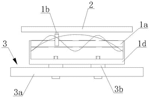
[0044] refer to Figure 4 , Figure 5 As shown, the linear ultrasonic micromotor of the present utility model includes a stator 1, a moving part 2 and a fixing mechanism 3. The stator 1 is composed of a thin-plate-shaped piezoelectric ceramic element 1a, a driving foot 1b and a base 1d. The base 1c is usually It is metal, such as copper; the fixing mechanism 3 is composed of a mounting plate 3a and an elastic pad 3b, and the elastic pad 3b is arranged between the mounting plate 3a and the base 1d; the piezoelectric ceramic element 1a is polarized along the length direction; the piezoelectric ceramic element 1a The upper and lower surfaces of the piezoelectric ceramic element 1a are respectively provided with electrodes 4, and the electrodes 4 on the upper and lower surfaces are composed of several small electrode surfaces. The electrode surfaces between the upper and lower s...

Embodiment 2

[0048] Example 2: Standing wave single piezoelectric ceramic plate and matrix composite linear ultrasonic micromotor

[0049] refer to Image 6 As shown, a kind of linear ultrasonic micromotor of the present invention, its structure is basically the same as embodiment 1, the difference is that the electrode 4 on the outer surface of the piezoelectric ceramic plate 1a is made of a plurality of electrode surfaces, and the other side uses On the surface bonded to the substrate 1c is an integral electrode 4, usually grounded. Its incentive mode and working principle are similar to those in Embodiment 1.

Embodiment 3

[0050] Example 3: One of the standing wave double piezoelectric ceramic plate and matrix composite linear ultrasonic micromotor

[0051] refer to Figure 7 As shown, the structure of the linear ultrasonic micromotor of the present invention is basically the same as that of Embodiment 2, the difference is that there are two piezoelectric ceramic elements 1a, which are respectively bonded on the upper and lower surfaces of the substrate 1c, and the two piezoelectric ceramic elements The electrode 4 on the outer surface of the element 1a is composed of multiple electrode surfaces, and the other surface bonded to the substrate 1c is an integral electrode 4, which is usually grounded.

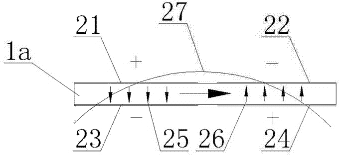
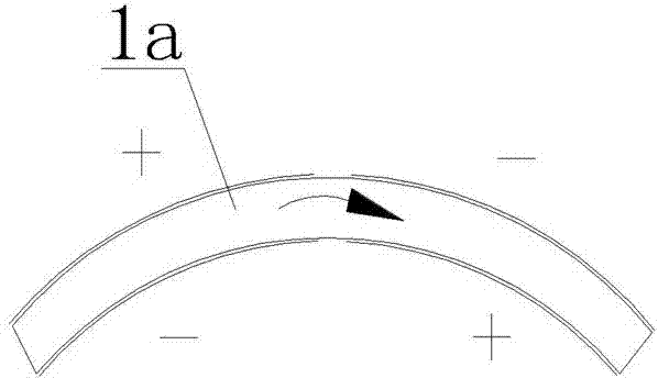
[0052] If two piezoelectric ceramic elements 1a are pasted in the opposite direction of polarization, when excited, an electric field is formed between each electrode surface of the piezoelectric ceramic element 1a and the other symmetrical electrode, and the direction of the electric field in the a...


PUM


Abstract

The invention discloses a linear type ultrasonic micromotor belonging to the technical field of ultrasonic micromotors and being technically characterized by comprising a stator, a moving part and a fixing mechanism, wherein the stator is mainly formed by bonding a piezoelectric ceramic element with driving feet; the piezoelectric ceramic element is in a thin plate shape and is polarized in a length direction, the upper surface and the lower surface of the piezoelectric ceramic element are both provided with electrodes, wherein the electrode on at least one surface is divided into a pluralityof small electrode surfaces, and the directions of excitation electric fields applied to the piezoelectric ceramic element by the two pairs of neighboring electrode surfaces are opposite. The invention aims at providing a linear type ultrasonic micromotor with large effective area of the electrode surfaces of the piezoelectric ceramic element, full polarization and high vibration efficiency, which is used in the fields of biology, medical treatment, micro machinery, national defense science and technology and the like.

Description

technical field [0001] The invention relates to an ultrasonic micromotor, more specifically, to a linear ultrasonic micromotor. Background technique [0002] Ultrasonic motors use the inverse piezoelectric effect of piezoelectric materials to convert electrical energy into vibration energy of the ultrasonic motor stator, and then convert it into rotation or linear motion of moving parts through friction. It is generally mainly composed of functional components such as a stator, a rotor (mover) and a pre-pressure mechanism. Compared with traditional electromagnetic motors, ultrasonic motors have many unique features and advantages, such as: [0003] (1) The structure is compact, the energy density (torque / mass) is high, and the motor is easy to miniaturize. [0004] (2) Low speed and high torque, without gear reduction mechanism, can realize direct drive. [0005] (3) The motor responds quickly and can realize self-locking when power is off. [0006] (4) Good position and...

Claims


Application Information

Patent Timeline
Patent Type & Authority Patents(China)
IPC IPC(8): H02N2/02H02N2/04
Inventor 钟侃生廖进华张发强张礼
Owner GUANGDONG JIAHE MICROMOTOR
Learn More