Gas-oil-water three-phase separator

A three-phase separator, gas-oil-water technology, applied in the direction of liquid separation, separation method, liquid degassing, etc., can solve the problems of releaser clogging, affecting production efficiency, complicated maintenance operations, etc., and achieve labor-saving maintenance and ideal results Effect

Active Publication Date: 2011-07-13
浙江海牛海洋工程有限公司
View PDF4 Cites 18 Cited by
  • Summary
  • Abstract
  • Description
  • Claims
  • Application Information

AI Technical Summary

Problems solved by technology

Since all kinds of releasers are installed inside the air flotation separator, because the releaser will often be blocked, it is necessary to increase the external energy cleaning system, and sometimes the entire air flotation separator needs to be stopped, and the releaser can only be repaired after it is emptied, and the maintenance operation is complicated. , troublesome, but also affect production efficiency
[0007] In summary, due to the limitations of the traditional horizontal three-phase separator in oil-water separation technology, the oil content in the final output water is still high, the separation effect is not ideal, and the volume is large, so it is not very suitable for high water content seas oil field production

Method used


Image

  • Gas-oil-water three-phase separator
  • Gas-oil-water three-phase separator
  • Gas-oil-water three-phase separator

Examples


Embodiment 1

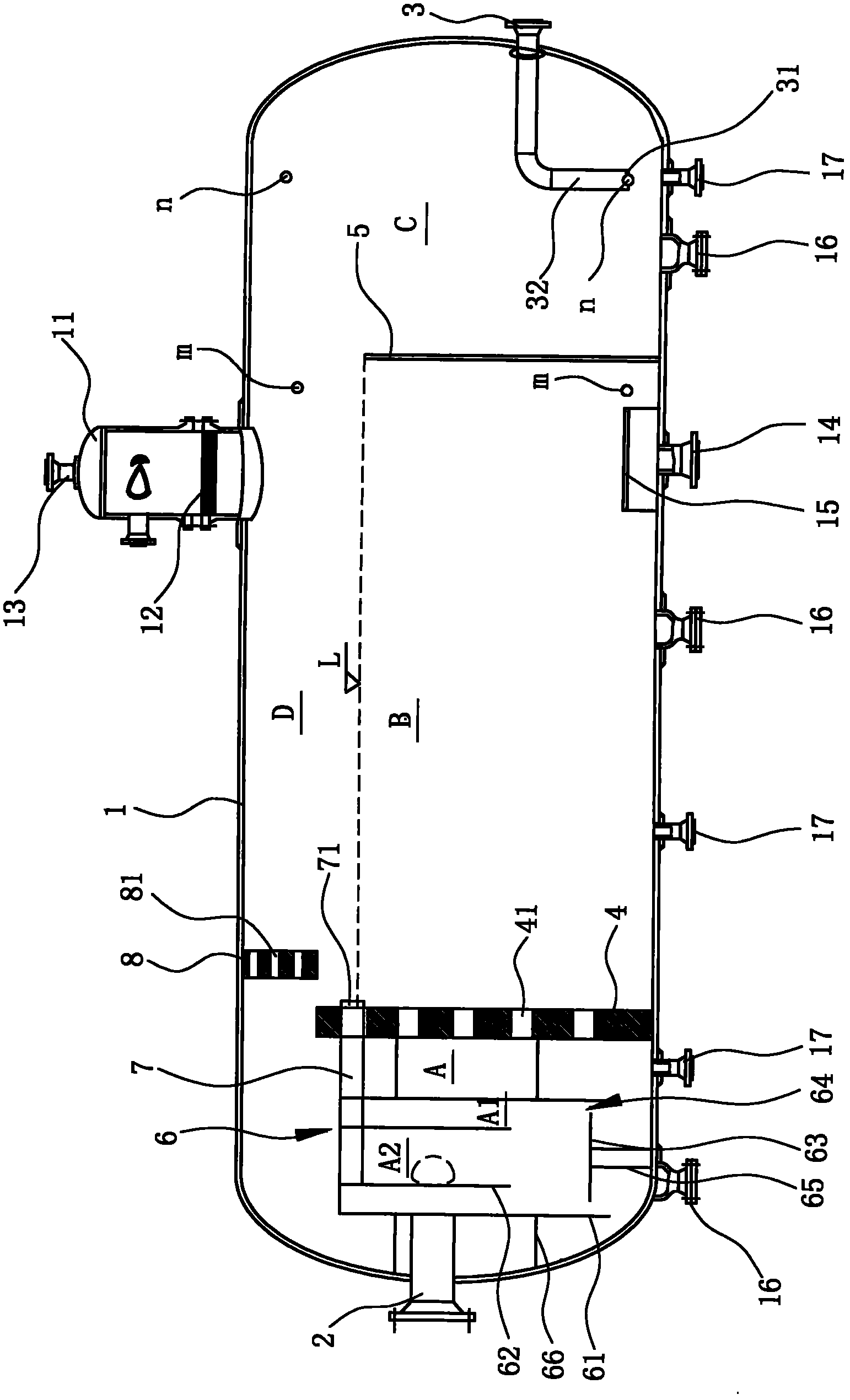
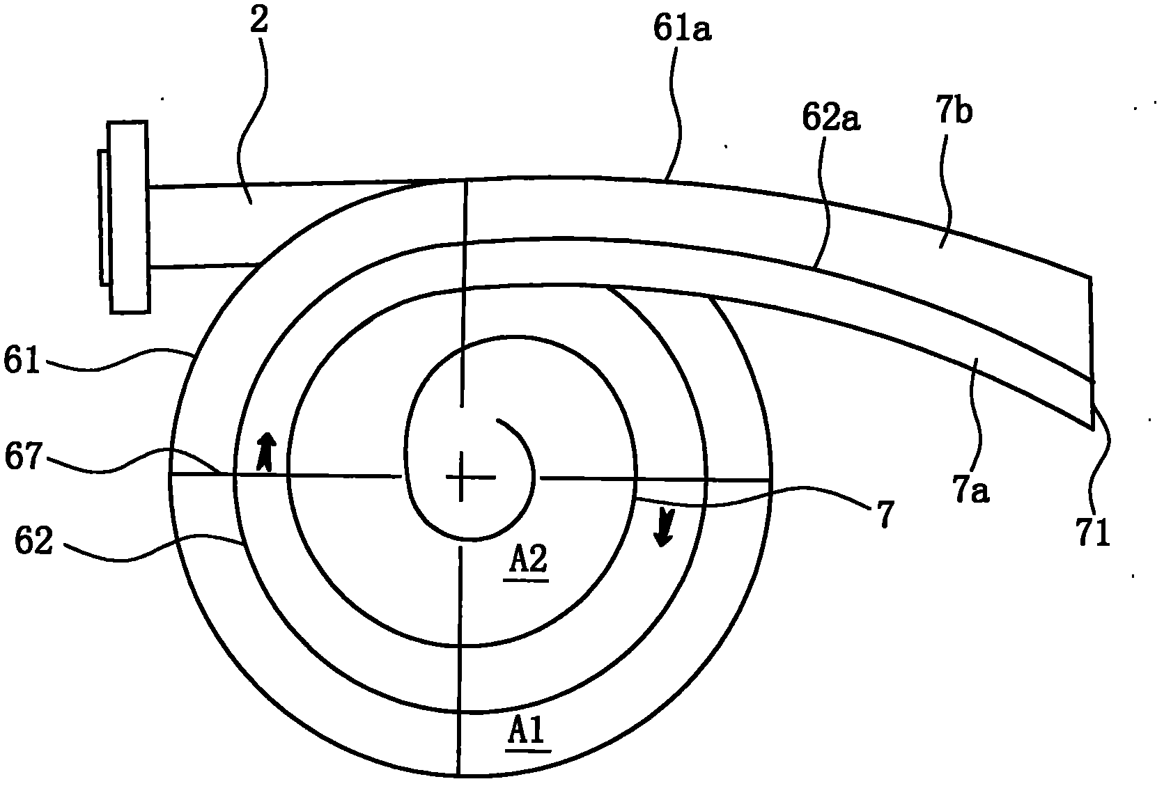
[0036] Such as figure 1 , figure 2 As shown, the gas-oil-water three-phase separator includes a horizontal tank body 1, a crude oil input pipe 2 and an oil discharge pipe 3;

[0037] Wherein, the interior of the tank body 1 is erected with a liquid stabilizing plate 4 and a baffle plate 5 in sequence from left to right, and the interior of the tank body 1 is divided into a separation area A, a liquid collection area B and an oil collection area in sequence from left to right. In zone C, the top of the liquid stabilizing plate 4 is higher than the baffle 5, and there is a gap between the tops of the liquid stabilizing plate 4 and the baffle 5 and the top of the tank 1, and the inside of the tank 1 is at the top of the baffle 5. A gas gathering area D is formed above;

[0038]The bottom of the tank body 1 is provided with a drainage pipe 14 at the position where the liquid collection area B is located and on the left side of the baffle plate 5;

[0039] The top of the tank b...

Embodiment 2

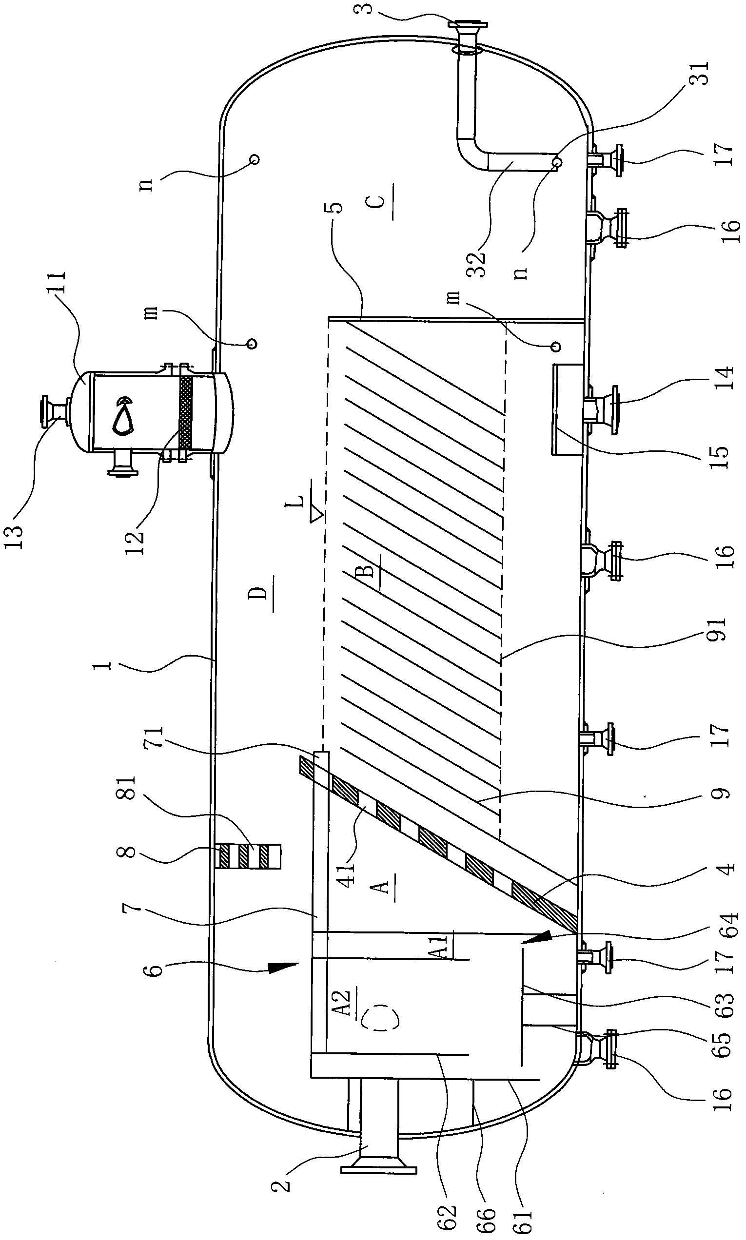
[0059] As shown in Figure 5, the difference between Embodiment 2 and Embodiment 1 of the present invention is that: the liquid stabilizing plate 4 is inclined in such a way that the top is inclined to the right, and there are multiple parallel plates in the liquid collection area B. And the corrugated plates 9 arranged at intervals form a corrugated plate group, the bottom of the corrugated plate closest to the liquid stabilizing plate 4 in the corrugated plate group is in contact with the bottom of the tank body 1, and the corrugated plate group is supported by a bracket 91 arranged at the bottom Fixed, in this embodiment, the corrugated plate 9 is also parallel to the liquid stabilizing plate 4 .

[0060] The liquid phase will pass through the corrugated plate 9 from top to bottom and enter the bottom area of ​​the tank 1, the oil phase will naturally float on the top of the liquid collection area B, and the water phase will be discharged from the tank 1 through the drain pip...


PUM


Abstract

The invention discloses a gas-oil-water three-phase separator which comprises a horizontal tank body (1) and a crude oil input tube (2), wherein a liquid steady flow plate (4) and a baffle (5) are sequentially erected in the tank body (1) from left to right so as to sequentially divide the interior of the tank body (1) into a separating area (A), a liquid collecting area (B) and an oil collectingarea (C); a gas collecting area (D) is arranged above the baffle (5); the bottom of the tank body (1) is provided with a drain tube (14), the top of the tank body (1) is provided with a convex gas collecting bag (11), and the right side end of the tank body (1) is provided with an oil drain tube (3); moreover, a sleeve-type cyclone separator (6) is arranged in the separating area (A) and comprises an outer sleeve (61) and an inner sleeve (62) which are concentrically arranged and parallel and level at the top; a gas-liquid separating area (A1) is arranged between the outer sleeve (61) and theinner sleeve (62); and a gas-water mixing area (A2) is arranged in the inner sleeve (62). Compared with the prior art, the gas-oil-water three-phase separator provided by the invention has the advantages that the repair and maintenance are labor-saving and convenient; for the same crude oil throughput, the volume of the horizontal tank body can be reduced, the gas-oil-water separating efficiency is obviously improved, and the separating effect is more ideal.

Description

technical field [0001] The present invention relates to the technical field of gas, oil and water separation treatment, especially refers to a kind of gas-oil-water three-phase separation process, which adopts the swirling flow method to separate gas-liquid, adopts gravity method and air flotation method to separate gas-liquid oil, and A high-efficiency gas-oil-water three-phase separator that finally realizes three-phase separation. Background technique [0002] The oily water in the production process of oil and natural gas comes from various links such as oil and natural gas exploitation, processing, refining, storage and transportation. Chemical agents and some microorganisms. [0003] Generally, the physical state of oil in oily water can be roughly divided into five types: slick oil, dispersed oil, emulsified oil, dissolved oil and solid-adhered oil. Usually, the above-mentioned physical states coexist. The commonly used physical treatment methods mainly include grav...

Claims


Application Information

Patent Timeline
Patent Type & Authority Applications(China)
IPC IPC(8): B01D17/025B01D19/00
Inventor 马立峰孙涛涛王建荣
Owner 浙江海牛海洋工程有限公司
Why Eureka
Try Eureka