LED fluorescent powder spraying process

A technology of phosphor powder and LED chip, applied in the direction of coating, the device for coating liquid on the surface, etc., can solve the problems of color area dispersion, uneven light output, yellow circle, basket circle, etc., to achieve consistency that is easier to control, thickness The effect of uniform, concentrated product color area

Inactive Publication Date: 2011-07-13
惠州市华阳光电技术有限公司
View PDF3 Cites 5 Cited by
  • Summary
  • Abstract
  • Description
  • Claims
  • Application Information

AI Technical Summary

Problems solved by technology

[0003] At present, the traditional glue dispensing process is to mix powder glue and defoam it on the surface. After baking, the surface of the LED chip will form an arc-shaped structure with a thick middle and thin sides, resultin

Method used


Image

  • LED fluorescent powder spraying process
  • LED fluorescent powder spraying process

Examples


Example Embodiment

[0016] Example 1

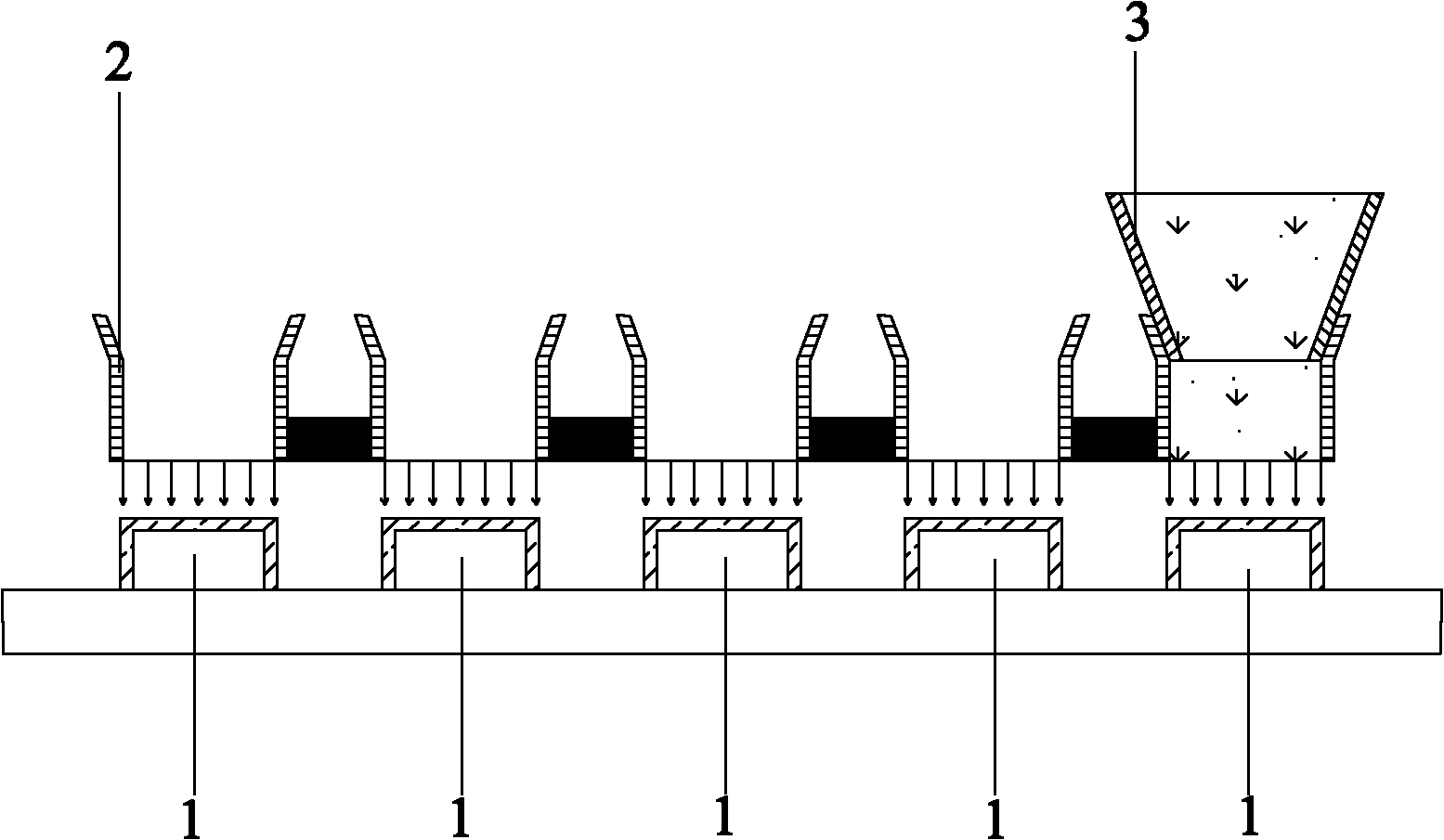
[0017] The LED phosphor spraying process provided in this embodiment includes the following steps:

[0018] (1) Mix the phosphor, glue and volatile solvent evenly to make a mixture of phosphors and load it in the glue sprayer; (2) Fix the bracket of the LED chip 1 that has been soldered on the fixture; 3) Make a mold according to the structure of the LED support and the chip 1. The baffle 2 of the mold is placed on the upper part of the LED chip 1 with a certain gap. The baffle 2 is at the same horizontal distance from the periphery of the LED chip 1; (4) Spray The glue machine 3 sprays the phosphor mixture on the surface of the chip 1 through the baffle 2. The baffle 2 controls the directionality of the spraying. The phosphor mixture completely surrounds the sides and top of the chip 1; 5) The heat transferred by the auxiliary heating system of the base of the support evaporates the volatile solvent. After the volatile solvent is evaporated, the remaining phosp...

Example Embodiment

[0019] Example 2

[0020] The LED phosphor spraying process provided in this embodiment includes the following steps:

[0021] (1) Mix the phosphor, glue and volatile solvent evenly to make a mixture of phosphors and load it in the glue sprayer; (2) Fix the bracket of the LED chip 1 that has been soldered on the fixture; 3) Make a mold according to the structure of the LED support and the chip 1. The baffle 2 of the mold is placed on the upper part of the LED chip 1 with a certain gap. The baffle 2 is at the same horizontal distance from the periphery of the LED chip 1; (4) Spray The glue machine 3 sprays the phosphor mixture on the surface of the chip 1 through the baffle 2. The baffle 2 controls the directionality of the spraying. The phosphor mixture completely surrounds the sides and top of the chip 1; 5) The heat transferred by the auxiliary heating system of the base of the support evaporates the volatile solvent. After the volatile solvent is volatilized, the remaining phos...


PUM


Abstract

The invention discloses a light emitting diode (LED) fluorescent powder spraying process, which comprises the following steps: (1) uniformly mixing fluorescent powder, a glue material and a volatile solvent to prepare mixed solution of the fluorescent powder, and loading the mixed solution in a glue spraying machine; (2) fixing the bracket of an LED chip which is soldered with a wire on a clamp; (3) making a mold according to the structure of the LED bracket and the LED chip, wherein the baffle plates of the mold are positioned on the upper part of the LED chip and form a certain gap with the upper part of the LED chip, and the horizontal distances between the baffle plates and the periphery of the LED chip are equal; (4) the glue spraying machine sprays the mixed solution of the fluorescent powder onto the surface of the chip through the baffle plates, wherein the mixed solution of the fluorescent powder covers the side faces and the top part of the chip completely; and (5) violating the volatile solvent with the left fluorescent powder coated on the chip, and loading and forming the appearance glue. Compared with the prior art, the LED chip manufactured by using the LED fluorescent powder spraying process has the advantages that: the thickness of fluorescent powder is more uniform; the color zones of the product are centralized; and the consistency is easier to control.

Description

technical field [0001] The invention relates to the field of LED processing, and specifically refers to an LED fluorescent powder spraying process. Background technique [0002] In the process technology of LED white light, the thickness of the phosphor layer excited by blue light seriously affects the luminous light efficiency of the phosphor and the light effect of the final product. The uniformity of the phosphor thickness also has a great influence on the consistency and yield of the product. Therefore, the phosphor coating technology has a significant impact on the LED manufacturing process. [0003] At present, the traditional glue dispensing process is to mix powder glue and defoam it on the surface. After baking, the surface of the LED chip will form an arc-shaped structure with a thick middle and thin sides, resulting in a large amount of phosphors with low excitation efficiency and poor light output. Even, and there will be yellow circles and baskets, the consiste...

Claims


Application Information

Patent Timeline
IPC IPC(8): B05D7/00B05C9/14B05C11/00
Inventor 郭晓君王峰
Owner 惠州市华阳光电技术有限公司
Why Eureka
Try Eureka