
Electronic fence alarm system

An electronic fence and alarm system technology, which is applied in the direction of anti-theft alarm mechanical start, electrical components, and alarms that rely on broken/disturbed straightened ropes/metal wires, etc., can solve the problems of high false alarm rate and no active defense , to achieve the effect of strong environmental adaptability

Inactive Publication Date: 2011-07-13
会东县华瑞科技有限责任公司
View PDF7 Cites 7 Cited by
  • Summary
  • Abstract
  • Description
  • Claims
  • Application Information

AI Technical Summary

Problems solved by technology

[0003] For civilian perimeter protection and alarm systems, infrared detection technology and infrared microwave double-detection technology are generally used, but these technologies have the disadvantage of high false alarm rate
[0004] Chinese utility model patent specification CN2703088Y (authorized announcement date: June 1, 2005) discloses a kind of "intelligent electronic fence", but the intelligent electronic fence can only detect the alarm when it is cut
[0005] Chinese invention patent application publication specification CN101520933A (disclosure date: September 2, 2009) discloses a "heartbeat detection electronic fence sensor system and detection method", Chinese invention patent application publication specification CN101582189A (disclosure date: November 2009 On the 18th, a "tension-type electronic fence perimeter anti-intrusion alarm system" was disclosed. The above two inventions belong to the prevention and alarm system for passive detection of the perimeter, without the function of active defense.

Method used


Image

  • Electronic fence alarm system
  • Electronic fence alarm system

Examples


Embodiment Construction

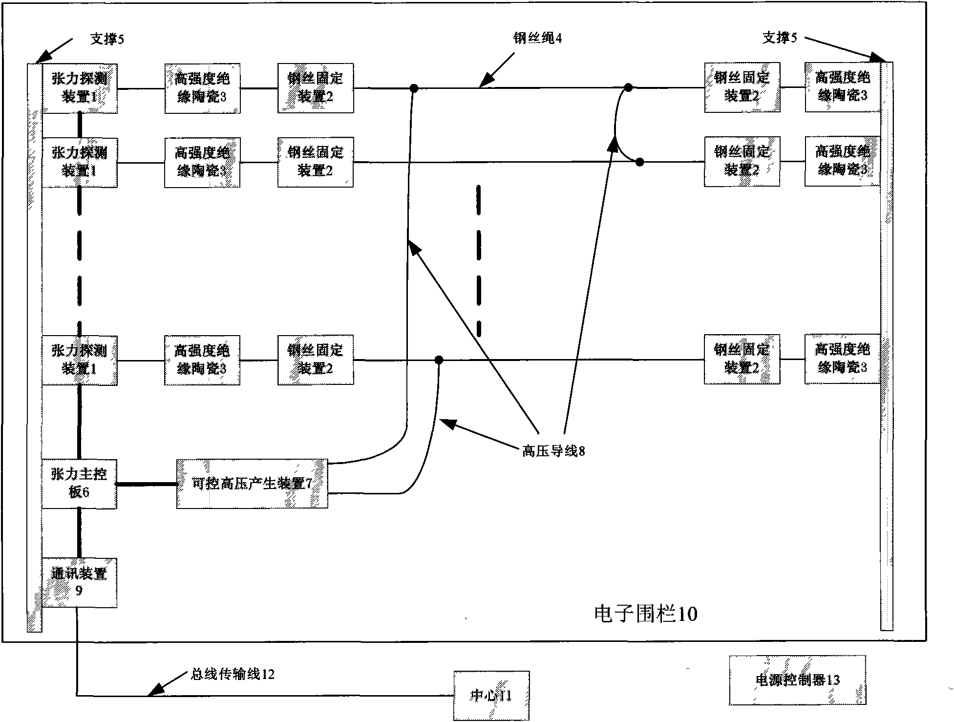
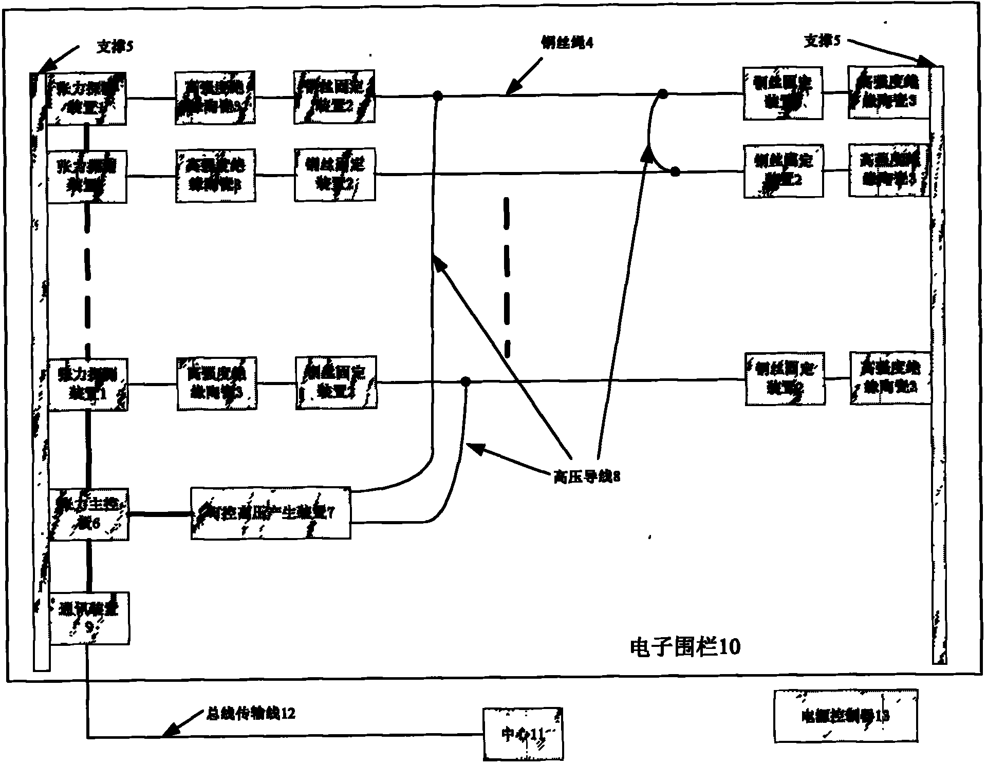
[0018] As shown in the figure, in an embodiment of the present invention, the electronic fence alarm system 10 includes: multiple stainless steel wire ropes 4, multiple wire fixing devices 2, multiple high-strength insulating ceramic terminals 3, and multiple tension detection devices 1. Tension main control board 6, high voltage generating device 7 and communication device 9; also includes remote control center 11 and power controller 13.

[0019] Located between the two support rods 5, a plurality of stainless steel wire ropes 4 are arranged in equal intervals from top to bottom. Both ends of each stainless steel wire rope 4 are respectively connected to a wire rope fixing device 2 , and each steel wire rope fixing device 2 is fixedly connected to a high-strength insulating ceramic terminal 3 respectively.

[0020] The high-strength insulating ceramic terminals 3 connected to one end of the plurality of stainless steel wire ropes 4 are fixedly installed on the support rod 5 ...


PUM


Abstract

The invention discloses an electronic fence alarm system. The system comprises a plurality of stainless steel wire ropes, a plurality of wire rope fixing devices, a plurality of high-strength insulating ceramic terminals, a plurality of tension detection devices, a main tension control board and a high-voltage generating device, wherein, the plurality of the stainless steel wire ropes are sequentially and alternately arranged from the top down and are connected in series through high-voltage leads; the plurality of the wire rope fixing devices are respectively connected on two ends of each stainless steel wire rope; two ends of each wire rope are respectively and sequentially connected with one wire rope fixing device and one high-strength insulating ceramic terminal, the high-strength insulating ceramic terminal on one end is arranged on a support bar, and the high-strength insulating ceramic terminal on the other end is connected with one tension detection device; the tension detection devices are fixedly arranged on the other support bar and are connected with the main tension control board; and the main tension control board is connected with the high-voltage generating device, is used for receiving and processing a tension signal, and controls the high-voltage generating device to generate high-voltage pulse in case of an alarm. The electronic fence alarm system has an active defense function without blind spots in perimeter precaution; and the system is adapted to various complex terrain environments without precaution dead space, thus being widely applicable to all places in need of perimeter precaution.

Description

technical field [0001] The invention relates to the field of safety protection, in particular to an electronic fence alarm system for perimeter protection and alarm. Background technique [0002] It is required in ordinary residential areas, villa residential areas, enterprises and institutions, factories, warehouses, substations, water plants, power plants, schools, detention centers and prisons of the judicial system, as well as airports, military bases, government agencies, key cultural relics protection units and other places. Perimeter security and intrusion alarm system. [0003] For civilian perimeter protection and alarm systems, infrared detection technology and infrared microwave double-detection technology are generally used, but these technologies have the disadvantage of high false alarm rate. [0004] Chinese Utility Model Patent Specification CN2703088Y (authorized announcement date: on June 1, 2005) discloses a kind of " intelligent electronic fence ", but, ...

Claims


Application Information

Patent Timeline
Patent Type & Authority Applications(China)
IPC IPC(8): G08B13/02G08B13/12H05C1/06G01L5/04
Inventor 唐智杰叶志锋李芳
Owner 会东县华瑞科技有限责任公司
Learn More