Capacitive detection type electro-mechanical transducer
An electromechanical transducer, capacitance detection technology, applied in capacitance measurement, measurement of electrical variables, measurement of resistance/reactance/impedance, etc., can solve the problem of narrowing detection bandwidth and achieve the effect of wide detection bandwidth
- Summary
- Abstract
- Description
- Claims
- Application Information
AI Technical Summary
Problems solved by technology
Method used
Image
Examples
no. 1 example
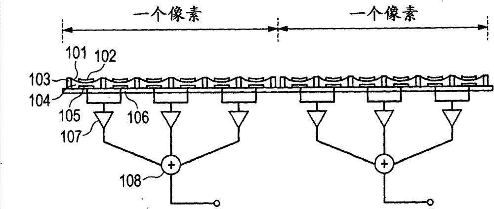
[0023] will refer to figure 1 A CMUT forming a capacitance detection type electromechanical transducer according to the first embodiment will be described.
[0024] In the CMUT according to the present embodiment, one pixel refers to an area in which ultrasonic wave information received by the vibrating membrane 101 is output as a piece of averaged information.
[0025] In one pixel, amplitude and phase information for ultrasonic waves are averaged, and a related apparatus forms an image of the subject based on the pixel-based amplitude and phase information.
[0026] The vibrating film 101 is supported by the supporting portion 103 formed on the substrate 106 . Each of the vibrating film 101 , the support portion 103 and the substrate 106 contains an insulating material.
[0027] The CMUT according to the present embodiment includes a detection electrode (first electrode) 105 arranged on a substrate 106 and a bias electrode (second electrode) 102, the bias electrode The (s...
no. 2 example
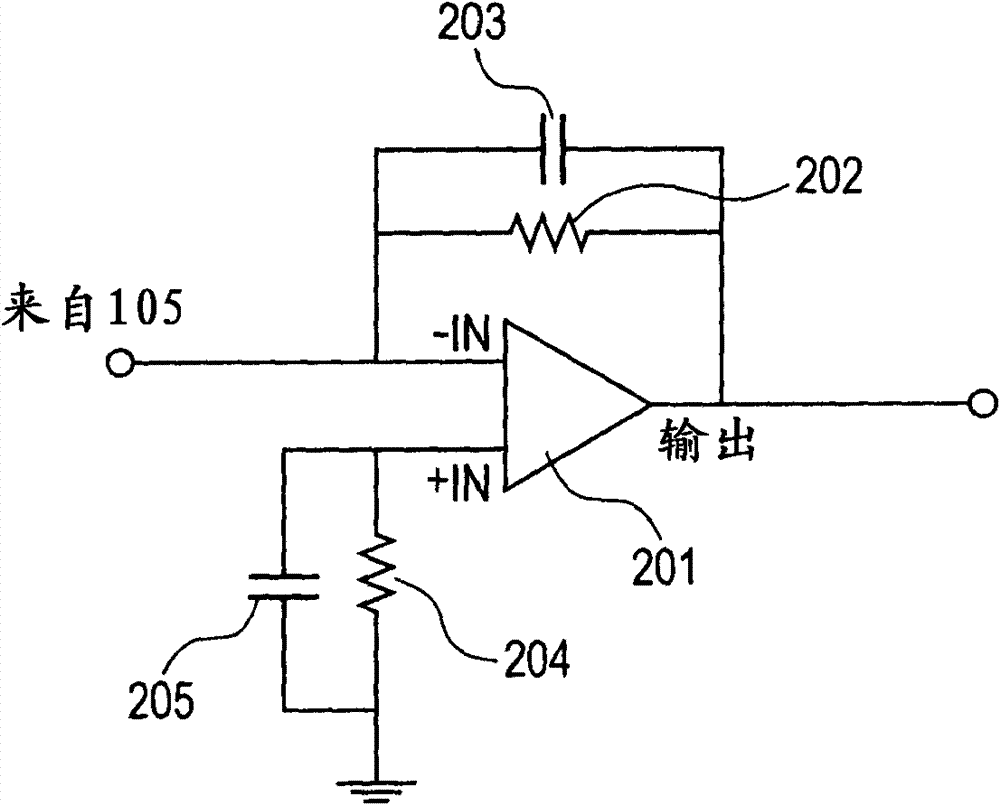
[0047] will refer to figure 2 A CMUT forming a capacitance detection type electromechanical transducer according to the second embodiment will be described.
[0048] figure 2 is a diagram of the configuration of a trans-impedance circuit
[0049] figure 2 The configuration in includes operational amplifier 201 , resistors 202 and 204 , and capacitors 203 and 205 . will refer to figure 1 to describe the figure 1 The parts in the corresponding parts.
[0050] The present embodiment is the same as the first embodiment except for the configuration of each detection circuit and the division count associated therewith. Here, the detection circuit 107 is a circuit for detecting a weak current generated by the vibration of the vibrating film.
[0051] In this embodiment, a transimpedance circuit is used, which is a current-voltage conversion circuit that converts a change in weak current into a voltage.
[0052] exist figure 2 , the operational amplifier 201 is connected to...
no. 3 example
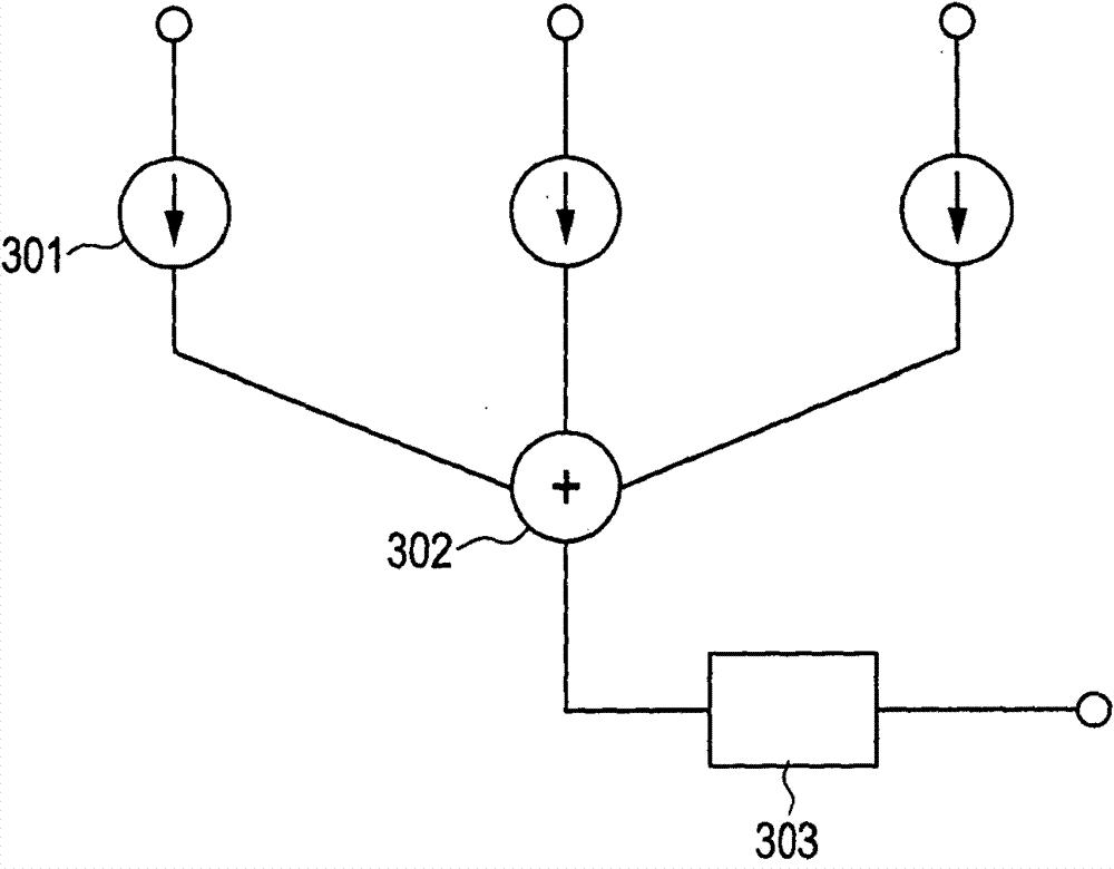
[0076] will refer to image 3 A CMUT forming a capacitance detection type electromechanical transducer according to the third embodiment will be described.
[0077] The present embodiment is the same as the first and second embodiments except for the configurations of the detection circuit and the addition circuit.
[0078] image 3 The illustrated configuration includes a current amplifying circuit 301 , a current adding circuit 302 and a current-voltage converting circuit 303 . The detection circuit 107 is formed by the current amplifying circuit 301 .
[0079] Further, the addition circuit 108 is formed by the current addition circuit 302 and the current-voltage conversion circuit 303 .
[0080] Each current amplification circuit 301 amplifies the weak current from the corresponding detection circuit 107 , performs impedance conversion, and outputs the resulting current to the addition circuit 108 .
[0081] In addition circuit 108 , a plurality of input currents are ad...
PUM
 Abstract
Description
Claims
Application Information
 - R&D
- Intellectual Property
- Life Sciences
- Materials
- Tech Scout
- Unparalleled Data Quality
- Higher Quality Content
- 60% Fewer Hallucinations
Browse by: Latest US Patents, China's latest patents, Technical Efficacy Thesaurus, Application Domain, Technology Topic, Popular Technical Reports.
© 2025 PatSnap. All rights reserved.Legal|Privacy policy|Modern Slavery Act Transparency Statement|Sitemap|About US| Contact US: help@patsnap.com


