Photoacoustic microfluidic detection system and detection method

A detection system and microfluidic technology, applied in chemical instruments and methods, measurement devices, material analysis by optical means, etc., can solve the problems of narrow bandwidth, insufficient sensitivity of small size, single frequency band, etc. The effect of small size, simple structure and wide detection band

Pending Publication Date: 2022-03-01
SHENZHEN UNIV
View PDF5 Cites 0 Cited by
  • Summary
  • Abstract
  • Description
  • Claims
  • Application Information

AI Technical Summary

Problems solved by technology

Ultrasonic transducers are made of piezoelectric materials. Due to the limitation of piezoelectric materials, the bandwidth of ultrasonic transducers is relatively narrow, the frequency band is single, the sensitivity of small sizes is insufficient, and the cost is high.
So far, there is no highly integrated photoacoustic detection system that can perform wide-bandwidth photoacoustic detection of microfluidics on the basis of simple structure and low cost.

Method used


Image

  • Photoacoustic microfluidic detection system and detection method
  • Photoacoustic microfluidic detection system and detection method
  • Photoacoustic microfluidic detection system and detection method

Examples


Embodiment 1

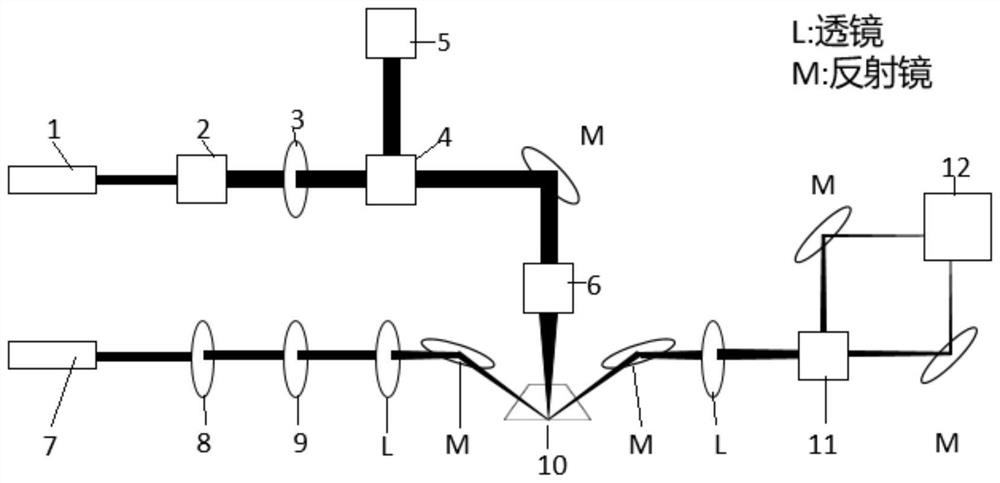
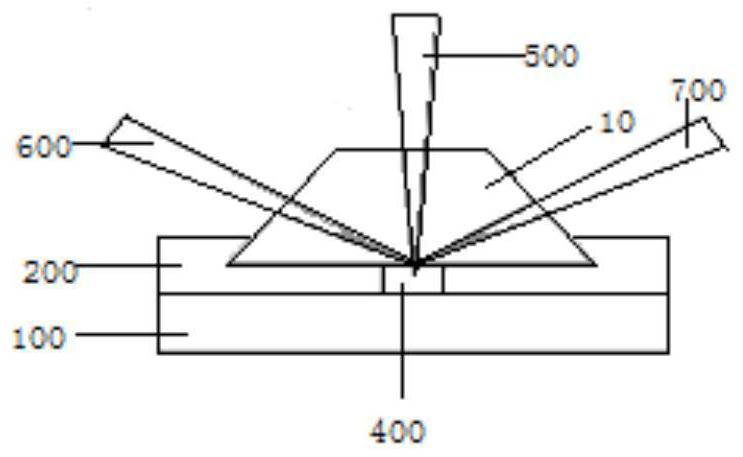
[0046] Such as figure 1 with figure 2 As shown, the laser excitation module includes a pulse excitation light source 1, a beam expander 2, a filter 3, a beam splitter 4, a mirror M, an objective lens 6 and a photoelectric probe. A pulsed laser light is emitted from the pulsed excitation light source 1, collimated and amplified by the beam expander 2, filtered by the filter 3, and split by the beam splitter 4, and one beam of light enters the photoelectric probe 5 as a subsequent signal processing module trigger signal. Another beam of light 500 is reflected by the mirror M and enters the objective lens 6, and is focused on the sample in the microfluidic channel 400 of the microfluidic chip to excite the sample to emit ultrasonic waves.

[0047] The laser detection module includes a continuous laser light source 7 , a polarizer 8 , a 1 / 4 wave plate 9 , a lens L, a mirror M, a polarization beam splitter 11 and a balanced light detector 12 . The continuous laser light source ...

Embodiment 2

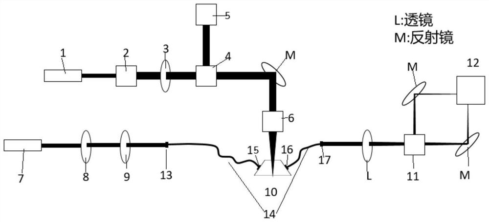
[0058] The laser excitation module in this example includes a pulse excitation light source 1, a beam expander 2, an optical filter 3, a beam splitter 4, a mirror M, an objective lens 6 and a photoelectric probe. A pulsed laser light is emitted from the pulsed excitation light source 1, collimated and amplified by the beam expander 2, filtered by the filter 3, and split by the beam splitter 4, and one beam of light enters the photoelectric probe 5 as a subsequent signal processing module trigger signal. Another beam of light 500 is reflected by the mirror M and enters the objective lens 6, and is focused on the sample in the microfluidic channel 400 of the microfluidic chip to excite the sample to emit ultrasonic waves.

[0059] The laser detection module of this example includes a continuous laser light source 7, a polarizer 8, a 1 / 4 wave plate 9, an optical fiber 14, fiber collimating mirrors 13, 15, 16, 17, a lens L, a polarization beam splitter 11 and a balanced light dete...

specific Embodiment approach 1

[0069] Such as Figure 5 As shown, in this embodiment, the pulse excitation light source 1 uses a 532nm pulse laser, the continuous laser light source 7 uses a HeNa laser, the polarizer 8 uses a polarizer, and the sample uses black tape. Black tape is attached to the tubes on the underside of the prisms in the microfluidic chip. The thickness of the pipes in the microfluidic chip is about 500 microns. The photoacoustic signal of the black tape in the 500 micron pipe displayed in the oscilloscope of the signal processing module is as follows: Image 6 shown.


PUM

PropertyMeasurementUnit
thicknessaaaaaaaaaa
thicknessaaaaaaaaaa

Abstract

The invention provides a photoacoustic microfluidic detection system and a detection method, and belongs to the technical field of photoacoustic detection. The detection system comprises a laser excitation module, a laser detection module, a micro-fluidic chip and a signal processing module, the micro-fluidic chip comprises a substrate, a micro-channel arranged on the substrate, a liquid inlet and a liquid outlet which are communicated with the micro-channel, and a prism arranged above the micro-channel, the laser excitation module is used for exciting a sample of the detection window to emit ultrasonic waves, and the laser detection module comprises a second laser light source, a second light path arranged on the incident side of the prism and used for processing the second laser light source, a third light path arranged on the reflecting side of the prism and a balanced light detector; the balanced light detector is used for converting the change of the intensity difference between the S polarized light and the P polarized light into a voltage signal; and the signal processing module is used for receiving, processing and displaying the voltage signal of the balanced light detector. The method is simple in detection mode and low in cost.

Description

technical field [0001] The invention relates to a photoacoustic detection technology, in particular to a photoacoustic microfluidic detection system and detection method. Background technique [0002] Microfluidics is a rapidly evolving tool that enables researchers to exercise unprecedented control over microscale environments. Microfluidics is being used in numerous fields, including biology, materials science, medicine, chemistry and physical sciences. Working inside the microchannels, researchers can manipulate individual components of their system of interest at high resolution. Systems of small size and volume have many other key advantages, including portability, low cost, rapid prototyping, easier automation, and the ability to work with limited sample sizes and reagents. As a result, microfluidic research has grown tremendously over the past 20 years, resulting in a plethora of microfluidic applications. [0003] Microfluidics mainly refers to a new type of techn...

Claims


Application Information

Patent Timeline
Patent Type & Authority Applications(China)
IPC IPC(8): G01N21/17G01N21/63B01L3/00
CPCG01N21/1702G01N21/63B01L3/5027G01N2201/06113
Inventor 蔡建芃吴佳霖方晖闫昇
Owner SHENZHEN UNIV
Why Eureka
Try Eureka