
Optical fiber grating acceleration sensor and test method thereof

A technology of acceleration sensor and fiber grating, which is applied in the direction of using inertial force for acceleration measurement, etc., can solve the problems of small cross-sectional area of ​​fiber grating, unbalanced initial state, and easy breakage, etc., to expand the range of strain range, improve sensitivity, increase non-linear effect

Inactive Publication Date: 2011-07-20
NANJING UNIV OF AERONAUTICS & ASTRONAUTICS
View PDF11 Cites 25 Cited by
  • Summary
  • Abstract
  • Description
  • Claims
  • Application Information

AI Technical Summary

Problems solved by technology

Because the cross-sectional area of ​​the fiber grating is very small and cannot be bent, this structure has the disadvantages that it is not easy to fix with the lever and it is easy to break when the force is directly applied to the bare fiber grating.
The sensor uses a single grating, which can only qualitatively reduce the influence of temperature on the central wavelength of the grating according to the difference in thermal expansion coefficient of the material, and cannot accurately realize temperature self-compensation
Once the design is determined, the change of the mass of the mass block will inevitably lead to the imbalance of the initial state of the system and make the fiber grating have a certain prestress, which reduces the range of the fiber grating strain gauge

Method used


Image

  • Optical fiber grating acceleration sensor and test method thereof
  • Optical fiber grating acceleration sensor and test method thereof
  • Optical fiber grating acceleration sensor and test method thereof

Examples


Embodiment Construction

[0026] Below in conjunction with accompanying drawing, technical scheme of the present invention is described in detail:

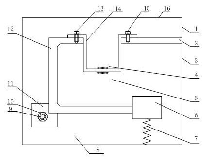
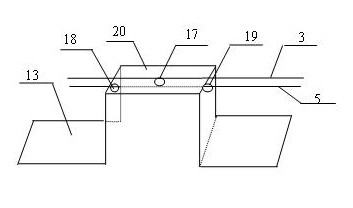
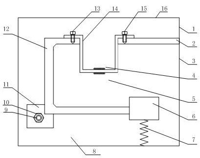
[0027] Such as figure 1 As shown, a fiber grating acceleration sensor includes a U-shaped housing 1, a rigid beam 2, a first fiber grating 4, a second fiber grating 5, a mass 6, a spring 7, a damping fluid 8, a slot 11, and a concave lever 12 , folding arched beam 14, sealing cover 16, the opening end of U-shaped housing 1 is provided with sealing cover 16, on the inner wall of U-shaped housing 1, connects one end of rigid beam 2, and the other end of rigid beam 2 is fixedly connected with folding arched beam 14, folding The arched beam 14 is fixedly connected with the concave lever 12, the concave lever 12 fixed on the slot 11 is connected to the mass block 6, the mass block 6 is connected to the inner wall of the housing 1 through the spring 7, and the first optical fiber is respectively arranged on the folded arched beam 14 The grating 4, the second fi...


PUM


Abstract

The invention discloses an optical fiber grating acceleration sensor and a test method thereof, relating to the technical field of optical fiber grating vibration sensing. The optical fiber grating acceleration sensor comprises a U-shaped shell, a steel beam, a first optical fiber grating, a second optical fiber grating, a mass block, a spring, damping fluid, a clamping groove, a concave lever, a folding arch beam and a seal cover, wherein the opening end of the U-shaped shell is provided with the seal cover; the inner wall of the U-shaped shell is connected with one end of the steel beam, and the other end of the steel beam is fixedly connected with the folding arch beam; the folding arch beam is fixedly connected with the concave lever; the concave lever fixed to the clamping groove is connected with the mass block; the mass block is connected with the inner wall of the shell by the spring; the first optical fiber grating and the second optical fiber grating are respectively arranged on the folding arch beam; and the damping fluid is filled in the U-shaped shell. The invention realizes the repeated design and use according to the engineering practical demand and changes the system rigidity by conveniently disassembling and replacing folding arch beams with different sizes, thereby realizing the adjustability of sensitivity and natural vibration frequency and achieving the aim of temperature self compensation.

Description

[0001] technical field [0002] The invention relates to the field of fiber grating acceleration sensor testing. Background technique [0003] Fiber grating acceleration sensors have important applications in many fields, such as real-time monitoring in aerospace, large electromechanical equipment, bridge structures, oil surveys, ships, and earthquakes. The fiber grating acceleration sensor embeds the fiber grating inside the substrate material and structure or pastes it on its surface to make it sensitive to the parameter to be measured, and senses the size of the parameter to be measured through the drift of the center wavelength, monitors the vibration of the object, and judges the work State, timely troubleshooting, to avoid major accidents. Traditional electrical acceleration sensors output weak electrical signals, cannot be transmitted over long distances, and have poor reliability in outdoor harsh environments, while fiber gratings can achieve long-distance monitor...

Claims


Application Information

Patent Timeline
IPC IPC(8): G01P15/03
Inventor 曾捷叶婷梁大开穆昊赵澎涛
Owner NANJING UNIV OF AERONAUTICS & ASTRONAUTICS
Learn More