Digital ray imaging voltage sensor

A voltage sensor, digital technology, applied in the direction of voltage/current isolation, using digital measurement technology for measurement, etc., can solve the problems of not achieving high and low potential electrical isolation, poor reliability, and small measurement range.

Inactive Publication Date: 2011-07-20
FUZHOU UNIV
View PDF3 Cites 4 Cited by
  • Summary
  • Abstract
  • Description
  • Claims
  • Application Information

AI Technical Summary

Problems solved by technology

Its advantage is to realize the optical isolation between high and low potentials, but the disadvantage is that the method of light intensity measurement is nonlinear, and is seriously affected by stress birefringence, the measurement range is small, and the reliability is poor
[0006] The active electronic type uses a capacitive voltage divider, a resistive voltage divider or an inductive voltage divider to obta...

Method used


Image

  • Digital ray imaging voltage sensor
  • Digital ray imaging voltage sensor
  • Digital ray imaging voltage sensor

Examples


specific Embodiment approach 1

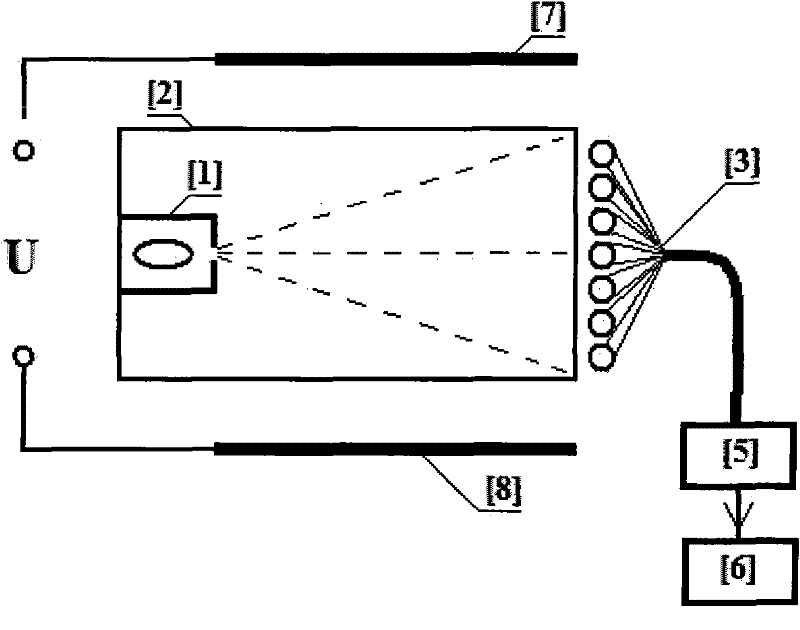
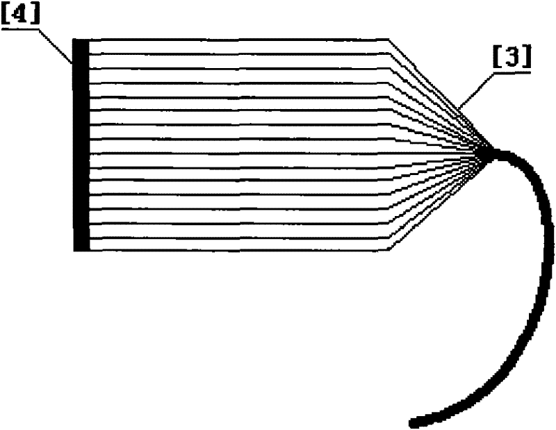
[0015] The specific implementation is as image 3 As shown, the isotope Sr90 radiation source [1] is placed in the vacuum glass body [2], the scintillation fiber bundle [3] is placed outside [2], [1] horizontally emits beta charged particles to [3] through a rectangular slit , bombarded with flashing fiber optic glow. The scintillation fibers are evenly arranged horizontally from top to bottom, the upper end is fixed with a reflective film [4] for reflecting photons, and the lower end is connected with an image intensifier [5]. The photons excited by the scintillation fiber are transmitted through the same fiber to [5] for enhanced amplification, and then to the image sensor [6] for signal processing. The voltage U to be measured is connected to the voltage plates [7] and [8], and [2] is placed between [7] and [8], and the electric field force between the plates drives the charged particles to generate the motion trajectory of the particles Change, bombarded to different pos...

specific Embodiment approach 2

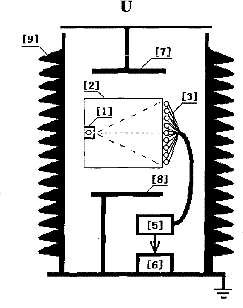
[0016] The second specific embodiment is as follows Figure 4 As shown, the isotope Sr90 radiation source [1] is placed inside the vacuum glass body [2], the scintillation fiber bundle [3] is placed outside [2], and [1] vertically emits beta charged particles to [3] through a rectangular slit , bombarded with flashing fiber optic glow. The scintillation fibers are evenly arranged horizontally from left to right, the upper end of which is fixed with a reflective film [4] for reflecting photons, and the lower end is connected to an image intensifier [5]. The photons excited by the scintillation fiber are transmitted through the same fiber to [5] for enhanced amplification, and then to the image sensor [6] for signal processing. The voltage U to be measured is connected to the voltage plates [7] and [8], and [2] is placed between [7] and [8], and the electric field force between the plates drives the charged particles to generate the motion trajectory of the particles Change, b...


PUM


Abstract

The invention relates to a digital ray imaging voltage sensor based on the principle and the ray imaging technique of the electric field force (voltage) upon the charged particles. A vacuum glass is arranged between voltage polar plates; an isotope ray source positioned in the vacuum glass emits an alpha or beta charged particles to bombard scintillation optical fibers to flash; the scintillation optical fibers are uniformly and horizontally arranged from up to down and from left to right, wherein the upper end of the scintillation optical fibers is fixedly provided with a reflecting film for reflecting photons; the lower end is connected with an image intensifier. The photons emitted by the scintillation optical fibers are transmitted to the image intensifier for amplifying through the same optical fiber, and then are subjected with signal processing photo through the image sensor. The voltage to be measured is connected with the voltage polar plate; and the driving force of the electric field force between the polar plates upon the charged particles can change the moving track of the particles. When bombarding the scintillation optical fibers at different positions, the corresponding lighting positions can be changed; the changing amount is in proportion to the amplitude of the electric field force (voltage); and the change of the lighting position is detected by adopting a digital image processing method to obtain the real time digital voltage signal. The measuring method of the invention is linear, high in level without power, so the method is suitable for the measurement of the alternating and direct current voltage of a power system.

Description

technical field [0001] The invention relates to a digital radiographic imaging voltage sensor, which is suitable for the measurement of AC and DC voltages of power systems based on the action principle of electric field force (voltage) on charged particles and radiographic imaging technology. Background technique [0002] At present, there are four types of voltage transformers or sensors that can be used for high voltage measurement: electromagnetic type, capacitive type, analog photoelectric type and active electronic type. [0003] The outstanding problems of electromagnetic voltage transformer in the application of ultra-high voltage and ultra-high voltage power system are its high electrical insulation cost and low reliability. Taking into account the requirements of safety, reliability, accuracy, cost performance, etc., electromagnetic voltage transformers are not suitable for high voltage levels. [0004] Capacitive voltage transformers are based on the principle of ...

Claims


Application Information

Patent Timeline
IPC IPC(8): G01R19/25G01R15/14
Inventor 徐启峰
Owner FUZHOU UNIV
Why Eureka
Try Eureka