
Conical scintillation crystal module and processing method thereof

A technology of scintillation crystals and processing methods, which is applied in the direction of measuring devices, instruments, scientific instruments, etc., can solve problems such as lack of data collection, achieve accurate cutting, improve imaging quality, and simple operation

Active Publication Date: 2011-07-20
NANJING RAYCAN INFORMATION TECH
View PDF4 Cites 26 Cited by
  • Summary
  • Abstract
  • Description
  • Claims
  • Application Information

AI Technical Summary

Problems solved by technology

[0005] The object of the present invention is to provide a conical scintillation crystal module and its processing method, which can effectively solve the problem of direct coupling between large-scale scintillation crystal modules and photoelectric conversion devices when there is no optical fiber or light cone conduction. The lack of acquisition can improve system sensitivity and image reconstruction quality. At the same time, this module has the potential to obtain the depth position information of visible light generated by energy deposition of high-energy particles in the scintillation crystal module through a certain calculation method, which can further improve the image reconstruction quality of the system; The processing method can realize high-precision cutting and processing of scintillation crystals, overcome the difficult problem of processing existing irregular-shaped scintillation crystal modules, and obtain high-precision conical scintillation crystal modules

Method used


Image

  • Conical scintillation crystal module and processing method thereof
  • Conical scintillation crystal module and processing method thereof
  • Conical scintillation crystal module and processing method thereof

Examples


Embodiment 1

[0031] Embodiment 1: A conical scintillation crystal module

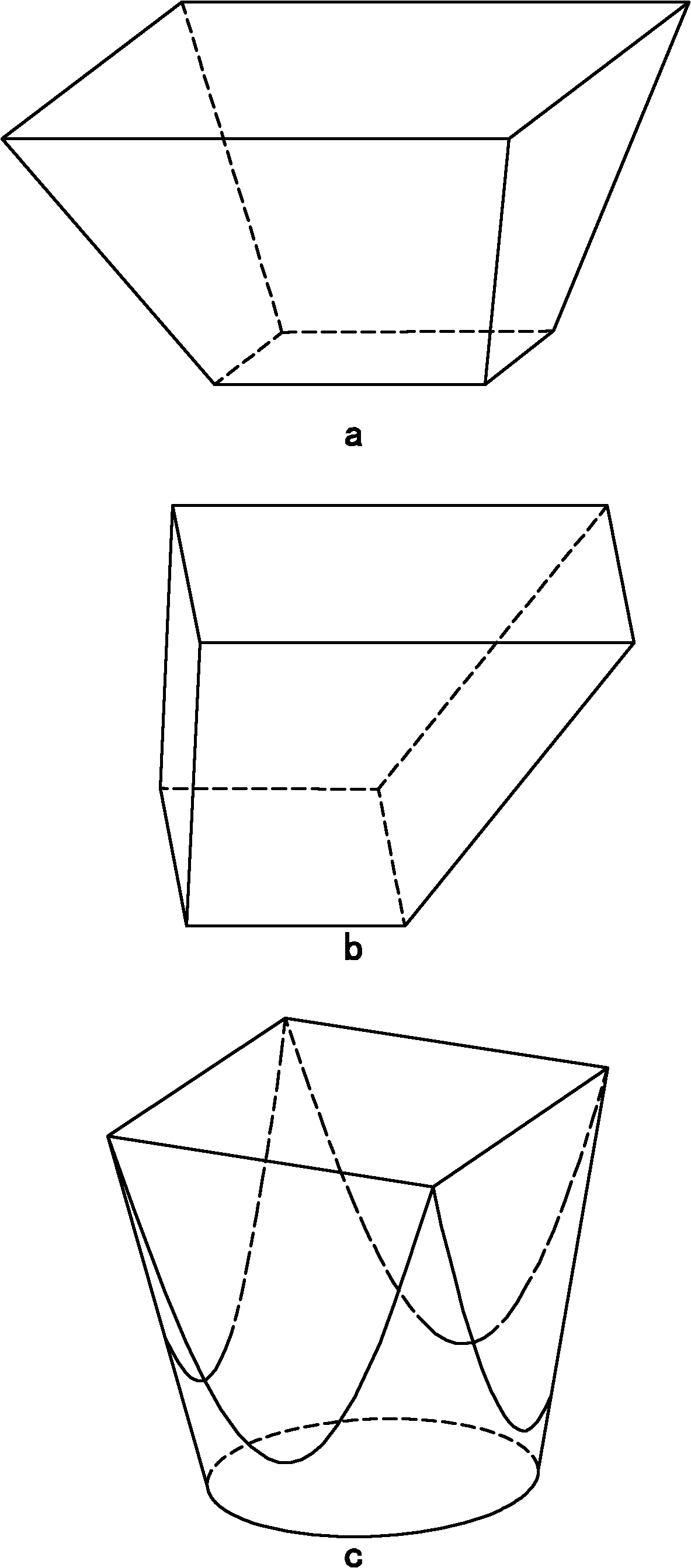
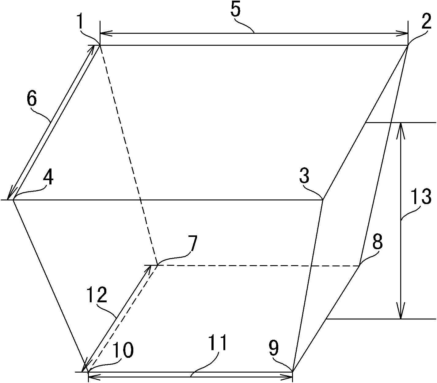
[0032] as attached figure 1 As shown in (a), a conical scintillation crystal module, the three-dimensional appearance of the conical scintillation crystal module is a conical frustum, the top surface and the bottom surface of the conical frustum are parallel to each other, both the top surface and the bottom surface are rectangular, and the top surface The area is greater than the area of ​​the bottom surface. Such as figure 2 As shown, the top length of the cone-shaped scintillation crystal module is defined as Top_length5, the width is Top_width6, the bottom surface length is Bottom_length11, the width is Bottom_width12, the distance between the top surface and the bottom surface is height13, and Top_length, Top_width, Bottom_length, Bottom_width, and height are all greater than zero. as attached Figure 4 As shown, the tapered scintillation crystal module is composed of an array of 4×3 crystal strips, where 4...

Embodiment 2

[0033] Embodiment 2: A conical scintillation crystal module

[0034] as attached figure 1 As shown in (b), a conical scintillation crystal module, the three-dimensional appearance of the conical scintillation crystal module is a conical frustum, the top surface and the bottom surface of the conical frustum are parallel to each other, both the top surface and the bottom surface are rectangular, and the top surface The area is greater than the area of ​​the bottom surface. Such as figure 2 As shown, the top length of the cone-shaped scintillation crystal module is defined as Top_length5, the width is Top_width6, the bottom surface length is Bottom_length11, the width is Bottom_width12, the distance between the top surface and the bottom surface is height13, and Top_length, Top_width, Bottom_length, Bottom_width, and height are all greater than zero. as attached Figure 5 As shown, the tapered scintillation crystal module is composed of an array of 12×6 crystal strips, wherei...

Embodiment 3

[0035] Embodiment 3: A conical scintillation crystal module

[0036] as attached figure 1 (a), (b) and appended Figure 6 As shown, a conical scintillation crystal module, the three-dimensional appearance of the conical scintillation crystal module is a conical frustum, the top surface and the bottom surface of the conical frustum are parallel to each other, both the top surface and the bottom surface are rectangular, and the area of ​​the top surface is larger than that of the bottom surface area. Such as figure 2 As shown, the four vertices on the top surface of the cone-shaped scintillation crystal module are defined clockwise as Top_A1, Top_B2, Top_C3, and Top_D4, and the four vertices corresponding to the bottom surface are Bottom_A7, Bottom_B8, Bottom_C9, and Bottom_D10. Among them, the vertices Top_X and Bottom_X form a cone-shaped scintillation A side edge of the crystal module, X=A, B, C, D, the direction of the straight line where the vertices Top_A and Top_B are...


PUM


Abstract

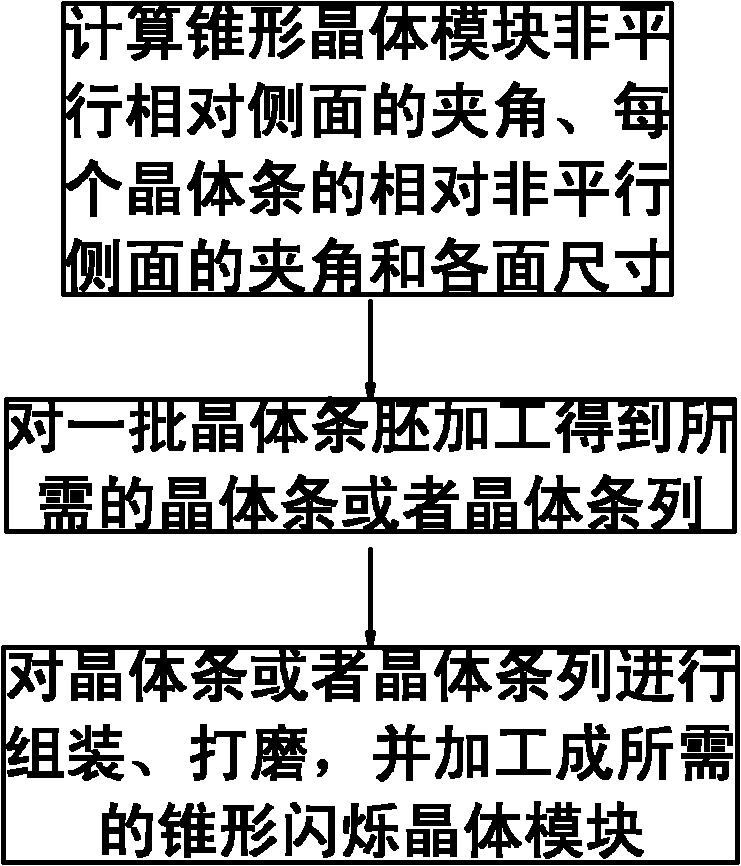
The invention discloses a conical scintillation crystal module and a processing method thereof. The stereo shape of the appearance of the scintillation crystal module is of a conical table, the top surface of the conical table is mutually parallel to the bottom surface, the top surface is rectangular, and the area of the top surface is greater than that of the bottom surface. The scintillation crystal module is formed by splicing and bonding m*n crystal strips. The processing method comprises the following steps of: calculating the size of each crystal strip according to the size of the conical scintillation crystal module and the array number of the crystal strips, assembling and polishing the crystal strips obtained by processing a batch of crystal strip blanks, and processing the crystal strips into the conical scintillation crystal module as required. By designing the conical scintillation crystal module directly coupled with a photoelectric conversion device, the advantages of improving the sensitivity of a medical imaging system, reducing the problems on data acquisition deletion and improving the imaging quality of the system can be achieved under the condition that the energy resolution and the time resolution of the system are not affected.

Description

technical field [0001] The invention relates to a design method and a processing method of a scintillation crystal module, which are mainly used in the fields of image nuclear medical diagnosis, industrial online non-destructive detection, high-energy particle detection and the like. Background technique [0002] Scintillation crystals refer to a large class of crystalline materials capable of converting X-rays, gamma rays, or other high-energy particles into visible light. As a key component of gamma cameras, positron emission tomography (PET) and computed tomography (CT), scintillation crystals can convert high-energy particles, such as gamma rays and X-rays, into The low-energy visible light photons are transmitted to the photoelectric conversion device coupled with it and converted into electrical signals. The electrical signals are processed by the back-end circuit to obtain the information required by the system, and finally the image is reconstructed. Therefore, para...

Claims


Application Information

Patent Timeline
Patent Type & Authority Applications(China)
IPC IPC(8): G01T1/202
Inventor 谢庆国朱俊刘晶晶郭宁吴永成
Owner NANJING RAYCAN INFORMATION TECH
Learn More