
Method for simulative generation of working condition curve of electric vehicle

A technology for electric vehicles and working conditions, applied in the direction of vehicle testing, measuring electricity, measuring electrical variables, etc., can solve problems such as time-consuming and laborious

Active Publication Date: 2011-07-20
HANGZHOU GOLD NEW ENERGY TECH
View PDF3 Cites 22 Cited by
  • Summary
  • Abstract
  • Description
  • Claims
  • Application Information

AI Technical Summary

Problems solved by technology

This method needs to count a large amount of real data, which is time-consuming and labor-intensive.

Method used


Image

  • Method for simulative generation of working condition curve of electric vehicle
  • Method for simulative generation of working condition curve of electric vehicle
  • Method for simulative generation of working condition curve of electric vehicle

Examples


Embodiment 1

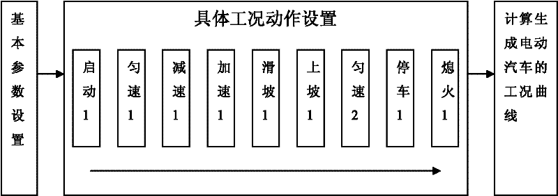
[0050] refer to Figure 5 , a method for simulating and generating electric vehicle operating condition curves, the flow chart of this embodiment is as follows figure 1 , including the following steps:

[0051](1) Set the basic information of the electric vehicle, including: vehicle shape (optional, divided into convertible car, box car body, foldback body, wedge-shaped body, K-shaped body, the best streamlined design), vehicle Type (optional, divided into sedan, canvas van, flatbed, van), vehicle curb weight, tire pattern (optional, divided into longitudinal, transverse, mixed, mud and snow, off-road, directional), tire width;

[0052] A specific example is as follows: vehicle curb weight: 1100kg, vehicle shape: streamlined design, electric vehicle type: sedan; tire pattern: longitudinal, tire width: 185mm.

[0053] Set the action type of the working condition, choose from start, constant speed, deceleration, acceleration, landslide, uphill, idle speed, stop or flameout;

...

Embodiment 2

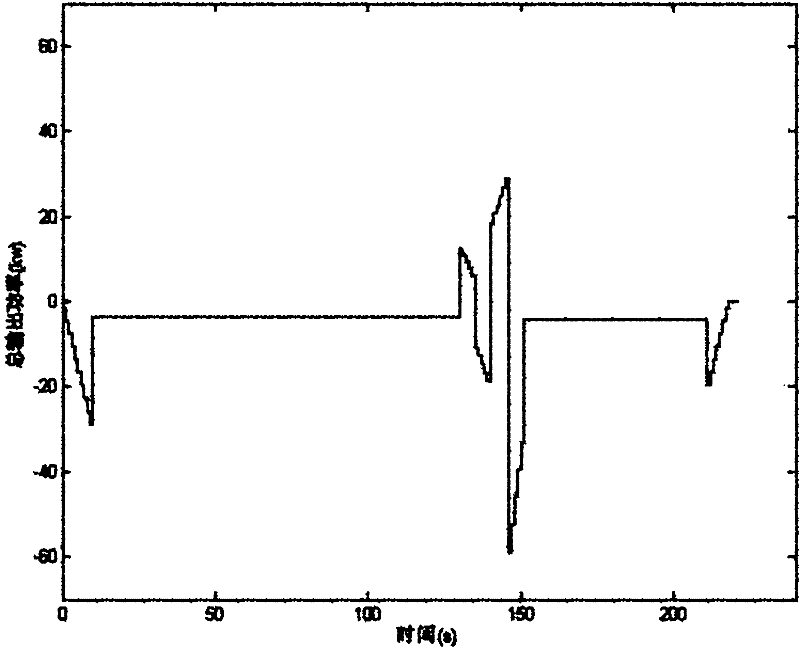
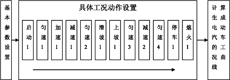
[0093] The flow chart of this embodiment is as image 3 , using the operating condition action type and parameters set in Table 9, other steps and parameters are the same as in Embodiment 1, and the corresponding electric vehicle operating condition curve can also be obtained, such as Figure 4 shown.

[0094] Table 9

[0095]

[0096]

[0097] To sum up, this patent is through the selection and setting of actions in various working conditions, and setting the execution order of each action, and finally simulates and generates the working condition simulation curve of the electric vehicle. Based on the generated working condition simulation curve, various This test is used to predict and analyze the dynamic performance of electric vehicle power batteries. This method has great flexibility and can simulate a variety of working conditions in reality, which greatly reduces the time and energy consumption of generating simulation curves of working conditions.


PUM

PropertyMeasurementUnit
Widthaaaaaaaaaa

Abstract

The invention relates to a method for the simulative generation of a working condition curve of an electric vehicle, which comprises the following steps of: setting basic information and more than one working condition action of the electric vehicle, wherein the basic information comprises vehicle shape, vehicle type, curb weight, tire tread and tire width, and the working condition action comprises working condition type and working condition parameters; calculating a quantitative relationship between output power and running time of an electric battery pack of the electric vehicle; and in accordance with the time interval of t2-t1=1s, obtaining the average output power of the electric battery pack of the electric vehicle within the time interval in order to obtain a relationship curve of the output power of electric battery pack of the electric vehicle and the time. The method for the simulative generation of the working condition curve of the electric vehicle has great flexibility, and is highly matched with the working conditions in real life, thereby remarkably reducing the time and the energy consumption required by generating a working condition simulating curve.

Description

(1) Technical field [0001] The invention relates to a method for simulating and generating an electric vehicle working condition curve. (2) Background technology [0002] In recent years, the technology of electric vehicles has been continuously matured, but the power battery and its group application technology are still the technical bottleneck of the development of electric vehicles. In practical applications, the power demand of electric vehicles on the motor is dynamically changing, and the instantaneous high current impact and the instantaneous switching between charging and discharging have put forward requirements on the dynamic performance of the power battery. Establishing a suitable power battery operating curve is of great significance for the prediction and evaluation of various dynamic performances of power batteries, and is also the basis for testing the life of electric vehicle batteries under dynamic working conditions. [0003] After simplifying the FUDS (...

Claims


Application Information

Patent Timeline
IPC IPC(8): G06F17/50G01M17/007G01R31/36
Inventor 王浩陈春飞徐剑虹
Owner HANGZHOU GOLD NEW ENERGY TECH
Learn More