Window control circuit for power factor correction circuit

A control circuit and circuit technology, applied in the direction of output power conversion device, high-efficiency power electronic conversion, electrical components, etc., can solve the problems of low efficiency and large switching loss, and achieve the reduction of switching loss, prevention of zero-crossing distortion, efficiency and The effect of power factor compromise

Active Publication Date: 2013-09-04
ZHEJIANG UNIV
View PDF4 Cites 0 Cited by
  • Summary
  • Abstract
  • Description
  • Claims
  • Application Information

AI Technical Summary

Problems solved by technology

Due to the characteristics of continuous input current, easy control, and low requirements for EMI filters, continuous current Boost PFC has been widely used. However, this circuit always works at a high switching frequency, and the switching loss is large. The problem of low efficiency at low input voltage

Method used


Image

  • Window control circuit for power factor correction circuit
  • Window control circuit for power factor correction circuit
  • Window control circuit for power factor correction circuit

Examples


Embodiment Construction

[0018] The present invention is described in detail below in conjunction with examples and accompanying drawings.

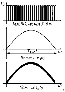
[0019] figure 1 The current continuous Boost PFC drive signal waveform, input voltage waveform and input current waveform are given. Such as figure 1 As shown, in the traditional continuous current Boost PFC, the switching tube always works at a high switching frequency, so the input current ripple is small, and a high input power factor can be obtained, but it also causes high switching loss, which affects The efficiency is further improved especially at light load or low input voltage. Since the switching loss is directly proportional to the switching frequency, the circuit efficiency can be improved by reducing the switching frequency. However, a lower switching frequency will cause larger current ripple and serious zero-crossing distortion, which will affect the power factor of the circuit. A compromise between switching frequency and power factor must be ...


PUM


Abstract

The invention discloses a window control circuit for a power factor correction circuit, which comprises a sinusoidal half-wave voltage sampling circuit, a low-pass filter circuit and a comparison circuit, wherein the output end of the sinusoidal half-wave voltage sampling circuit is connected with the low-pass filter circuit; and the output end of the half-wave voltage sampling circuit and the output end of the low-pass filter circuit are connected with two input ends of the comparison circuit, and different connection ways can be adopted according to whether oscillating capacitance or oscillating resistance is used for deciding switching frequency of a PFC (power factor correction) controller. By adopting the window control circuit, the higher switching frequency is adopted in a region with smaller loss of the power factor correction circuit, that is the regions on two sides of voltage half-waves of an input power grid, the zero-crossing distortion of current of the input power grid can be prevented, and a higher power factor can be ensured; and the lower switching frequency is adopted in the main loss generation region, that is the middle region of the voltage half-waves of the input power grid, thereby reducing switching loss and improving the efficiency of the circuit.

Description

technical field [0001] The present invention relates to a power factor correction (Power Factor Correction, hereinafter referred to as PFC) circuit, in particular to a window control circuit for a power factor correction circuit. Background technique [0002] Due to the wide application of power electronic equipment, the phenomenon of harmonic pollution is becoming more and more serious. Many international standards such as IEC61000-3-2 and IEEE519-992 have proposed restrictions on the harmonics injected into the grid by power electronic equipment, so it is necessary to add a power factor correction link before the switching power supply. Due to the characteristics of continuous input current, easy control, and low requirements for EMI filters, continuous current Boost PFC has been widely used. However, this circuit always works at a high switching frequency, and the switching loss is large. The problem of low efficiency at low input voltage. Contents of the invention ...

Claims


Application Information

Patent Timeline
Patent Type & Authority Patents(China)
IPC IPC(8): H02M1/42
CPCY02B70/126Y02B70/10
Inventor 徐德鸿柳绪丹岳衡林平胡长生潘航文
Owner ZHEJIANG UNIV
Why Eureka
Try Eureka