Elevator speed governor

A technology of speed limiter and elevator, applied in elevators, transportation and packaging, etc., can solve problems such as difficulty, low degree of freedom of flying pendulum, complicated assembly and adjustment operations, etc.

Inactive Publication Date: 2011-07-20
MITSUBISHI ELECTRIC CORP
View PDF1 Cites 5 Cited by
  • Summary
  • Abstract
  • Description
  • Claims
  • Application Information

AI Technical Summary

Problems solved by technology

[0007] Therefore, when the speed governor is assembled and adjusted, the displacement of the flying pendulum related to the operation of the overspeed switch and the rope gripping mechanism, the respective spring forces of the first balance spring and the second balance spring, and the force passing through the second balance spring Elements such as the distance between the baffle plate and the stopper plate on the rod are related to each other, and there are many adjustment parts, so there is a problem that the assembly and adjustment work is complicated, difficult, and time-consuming, and the structure of the overspeed governor becomes complicated. topic
[0008] In addition, in Image 6 In any one of the existing speed governors for elevators shown in Patent Document 1...

Method used


Image

  • Elevator speed governor
  • Elevator speed governor
  • Elevator speed governor

Examples


no. 1 approach

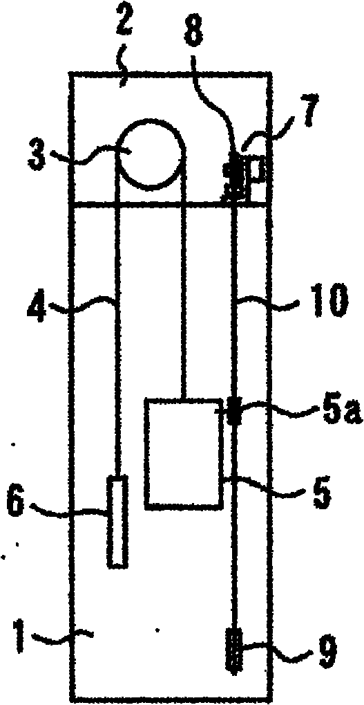
[0022] figure 1 and figure 2 Regarding the first embodiment of the present invention, figure 1 is the front view of the elevator speed limiter, figure 2 It is a schematic configuration diagram showing the outline of the overall configuration of the elevator.

[0023] In the figure, numeral 1 is the shaft of an elevator, and a machine room 2 is arranged at the upper end of the shaft 1 . A driver 3 for electrically driving the elevator is provided in the machine room 2 , and a main rope 4 is wound around a driving sheave of the driver 3 . In addition, a car 5 is connected to one end of the main rope 4, and the car 5 is arranged in the hoistway 1 so as to be able to move up and down freely. A counterweight 6 is connected to the other end of the main rope 4, and the counterweight 6 For the purpose of compensating the weight of the car 5, it is arranged in the hoistway 1 so as to be able to move up and down freely.

[0024] In the machine room 2 , a speed limiter 7 is prov...

no. 2 approach

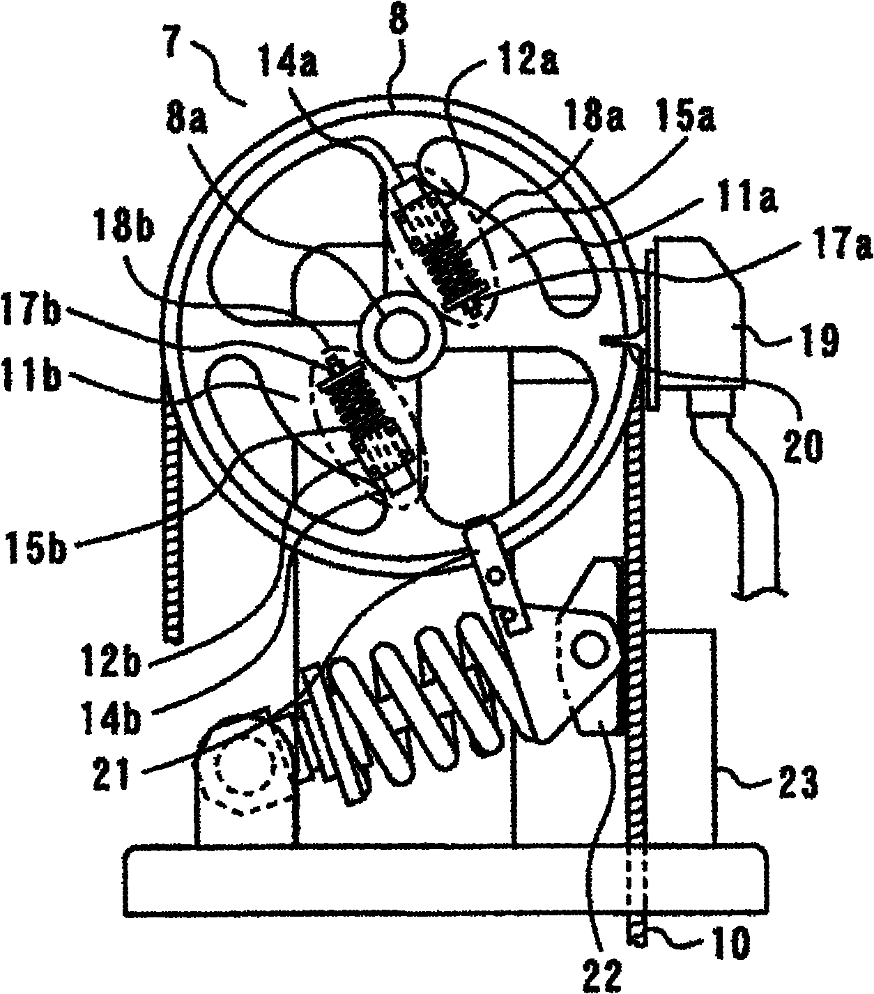
[0053] image 3 It is a front view of the speed governor for elevators concerning 2nd Embodiment of this invention.

[0054] In the above-mentioned first embodiment, the center of rotation of the sheave is located on the extension line of the movement trajectories of the first flying weight and the second flying weight, in other words, the moving directions of the first flying weight and the second flying weight However, in the second embodiment described here, the center of rotation of the sheave is not located on the extension line of the movement trajectories of the first flying pendulum and the second flying pendulum, in other words , and the moving directions of the first flying pendulum and the second flying pendulum are not arranged on the diameter of the sheave.

[0055] That is, at the spoke portion of the sheave 8, a fan-shaped first bearing fixing portion 11a having a central angle substantially at a right angle is formed, and a first linear motion is fixed to the fi...

no. 3 approach

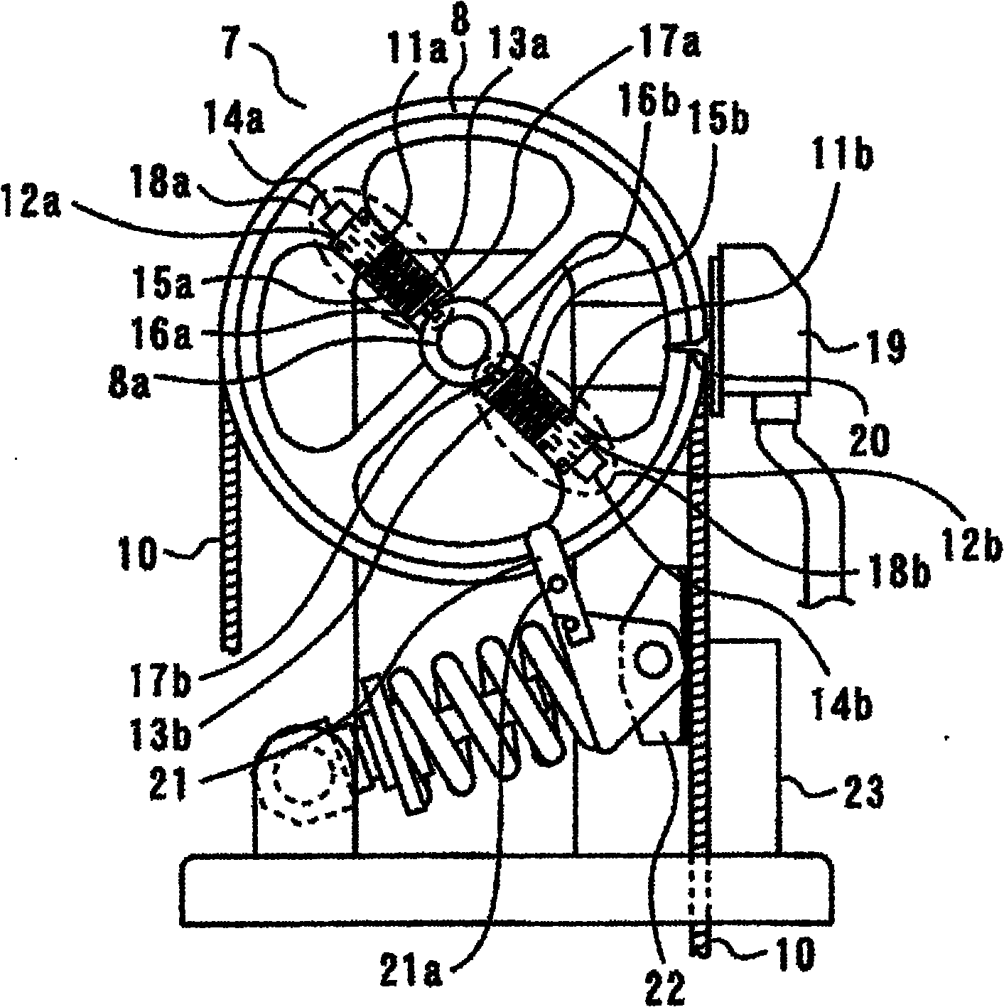
[0063] Figure 4 It is a front view of the speed governor for elevators concerning 3rd Embodiment of this invention.

[0064] In the third embodiment described here, in the above-mentioned second embodiment, a plurality of the first linear motion bearings 12 a and the second linear motion bearings 12 b are respectively provided.

[0065] That is, if Figure 4 As shown, a plurality of (here, two) first linear motion bearings 12a are fixed to the first bearing fixing portion 11a. In addition, accompanying this, the length dimension of the said 1st rod 13a is also longer than 2nd Embodiment. In addition, similarly, a plurality of (here, two) of the second linear motion bearings 12b are fixed to the second bearing fixing portion 11b, and accordingly, the length dimension ratio of the second rod 13b is The second embodiment is long.

[0066] In addition, other structures and operations are the same as those of the second embodiment.

[0067] In the second embodiment, since the...


PUM


Abstract

Provided is an elevator speed governor of simple construction that is easy to assemble and adjust and that has a high degree of freedom with respect to the arrangement of the fly weight, over-speed switch, and rope catch mechanism and setting of the fly weight mass, wherein arrangement of the fly weight, etc. and fly weight mass, etc. can be specifically determined for each of a first and a second over-speed detection speed, and which allow precise detection of each of said first and second over-speed detection speeds. Thus, the speed governor, which detects that the speed of travel of a passenger car has reached the first and second over-speed detection speeds in order to stop the passenger car, is equipped with a first over-speed detection mechanism that detects that the passenger car has reached the first over-speed detection speed and a second over-speed detection mechanism that is provided separately from the first over-speed detection mechanism and detects that the passenger carhas reached the second over-speed detection speed, and the first over-speed detection mechanism and the second over-speed detection mechanism are constituted to operate independently from one another.

Description

technical field [0001] The invention relates to a speed governor for an elevator. Background technique [0002] In the existing elevator speed limiter, such as Figure 6 Shown is a known speed governor for an elevator, which includes: a sheave 8, which is supported by a sheave shaft 8a so as to be able to rotate freely; a speed governor rope 10, which is looped is hung between the sheave 8 and the tensioning wheel in a shape, and circulates synchronously with the elevator car. The tensioning wheel can be freely rotatably arranged at the lower part of the hoistway; a pair of flying pendulums 14, the A pair of flying pendulums 14 can be freely rotatably arranged on the sides of the sheave 8; a connecting rod 25, which connects the pair of flying pendulums 14; a balance spring 15, the balance spring 15 follows the The rotation of the sheave 8 exerts force on the flying pendulum 14 in the direction opposite to the centrifugal force acting on the flying pendulum 14; the overspee...

Claims


Application Information

Patent Timeline
IPC IPC(8): B66B5/04
CPCB66B5/044B66B5/04
Inventor 新川岳史
Owner MITSUBISHI ELECTRIC CORP
Why Eureka
Try Eureka