Dual-temperature energy storage tank

A technology of thermal energy storage, thermal growth, applied in the field of design improvement, which can solve the problem of loss barrier isolation ability and so on

Inactive Publication Date: 2011-07-20
SENER ING Y SISTEMAS
View PDF3 Cites 10 Cited by
  • Summary
  • Abstract
  • Description
  • Claims
  • Application Information

AI Technical Summary

Problems solved by technology

In this way, a considerable amount of the isolation capability of the barrier is lost

Method used


Image

  • Dual-temperature energy storage tank
  • Dual-temperature energy storage tank

Examples


Embodiment Construction

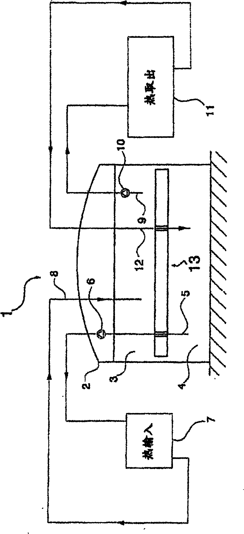
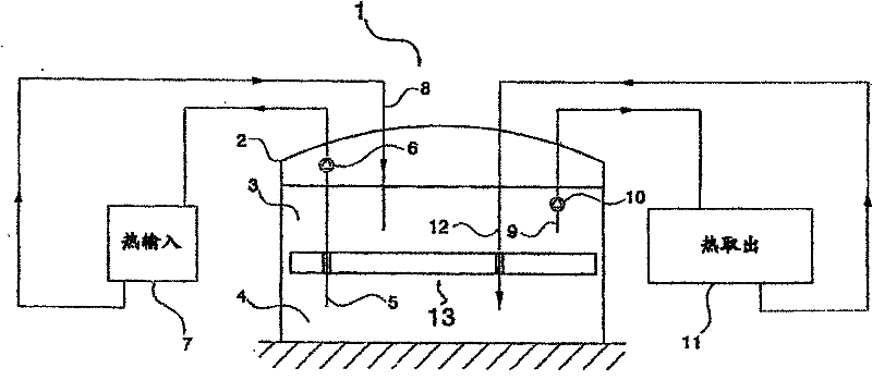
[0062] figure 1 A schematic arrangement of a heat storage system ( 1 ), which may be a storage system of a solar power plant, is shown. The storage system (1) comprises a thermocline storage tank (2) storing two portions of fluid at different temperatures. The cooler portion of fluid (4) is generally denser than the warmer portion of fluid (3), and the cooler portion of fluid (4) is stored below the warmer portion of fluid (3). The tank may typically be of the vertical cylindrical type with a diameter of about 40m and a height of about 15m. In many common solar applications, the cold fluid will typically be at a temperature of about 300°C and the hot fluid will be at a temperature of about 400°C, and the fluid stored at both temperatures will typically be a mixture of molten nitrates.

[0063] figure 1 The barrier of the present invention indicated schematically by reference numeral (13) in , is aimed at the interface between the hot and cold fluids to physically separate a...


PUM


Abstract

The invention relates to a thermocline storage tank including a barrier element which floats between two fluids stored at different temperatures, physically separating said fluids and isolating same. The floating barrier has multiple design characteristics that broaden the scope of application thereof, enabling same to be used in fields such as those involving the use of heat storage systems of solar generating plants.

Description

technical field [0001] The present invention relates generally to the field of thermal energy storage systems, and more particularly to improvements in the design of thermocline storage tanks. Background technique [0002] Thermal energy storage systems are often used in applications where energy harvesting must be decoupled from energy delivery. Solar harvesting systems are a typical example of this application, since there is usually a demand for energy during periods of no solar radiation, when energy cannot be harvested, energy is still delivered to meet the demand. [0003] Solar energy collection systems can range in size from small domestic collector systems used to heat water to much larger collector systems such as those found in solar power plants. [0004] One way of storing thermal energy involves exploiting the sensible heat of the fluid. During periods of solar radiation, thermal energy is stored by heating the fluid so that during periods of absence of solar...

Claims


Application Information

Patent Timeline
Patent Type & Authority Applications(China)
IPC IPC(8): F28D20/00
CPCF24D2200/14F24D11/00F28D2020/0047Y02E60/142F28D20/0039Y02E70/30Y02B10/20F28D2020/0095Y02E60/14
Inventor J·M·拉塔佩雷茨J·布兰科洛伦佐
Owner SENER ING Y SISTEMAS
Why Eureka
Try Eureka