
Crop drying equipment

A technology for drying equipment and crops, applied in food science, application, food processing, etc., can solve the problems of sporadic processing and impractical family workshop processing, and achieve the effect of saving labor intensity and using less labor

Inactive Publication Date: 2011-07-27
朱延根
View PDF7 Cites 7 Cited by
  • Summary
  • Abstract
  • Description
  • Claims
  • Application Information

AI Technical Summary

Problems solved by technology

[0004] After searching the existing patent documents, it is found that the Chinese patent "patent name, a raisin washing and drying device; application date, December 31, 2004; authorized publication number, CN2762564Y" discloses a raisin washing and drying device, including raisin Conveyor belt, dehydrator and drying box, and above the horizontal conveying surface of the raisin conveyor belt, drooping high-pressure water nozzles are uniformly arranged, and a bottomless conical feeding funnel is arranged on the top of the dehydrator, which is located in the raisin conveying Below the blanking end of the belt, a conical dehydration barrel is set upside down in the shell of the dehydrator. The lower part of the feeding funnel is located in the dehydration barrel. The bottom surface of the dehydrator shell under the dehydration bucket is an inclined surface, and the bottom of the bottom surface of the dehydrator shell is provided with a discharge port. The technical feature of the discharge port is connected to the drying box; but in actual operation, it is only suitable for large-scale processing enterprises. It is not practical for sporadic processing and family workshop processing

Method used


Image

  • Crop drying equipment
  • Crop drying equipment
  • Crop drying equipment

Examples


Embodiment Construction

[0025] The present invention can be explained in more detail by the following examples, the present invention is not limited to the following examples, the purpose of disclosing the present invention is intended to protect all changes and improvements within the scope of the present invention;

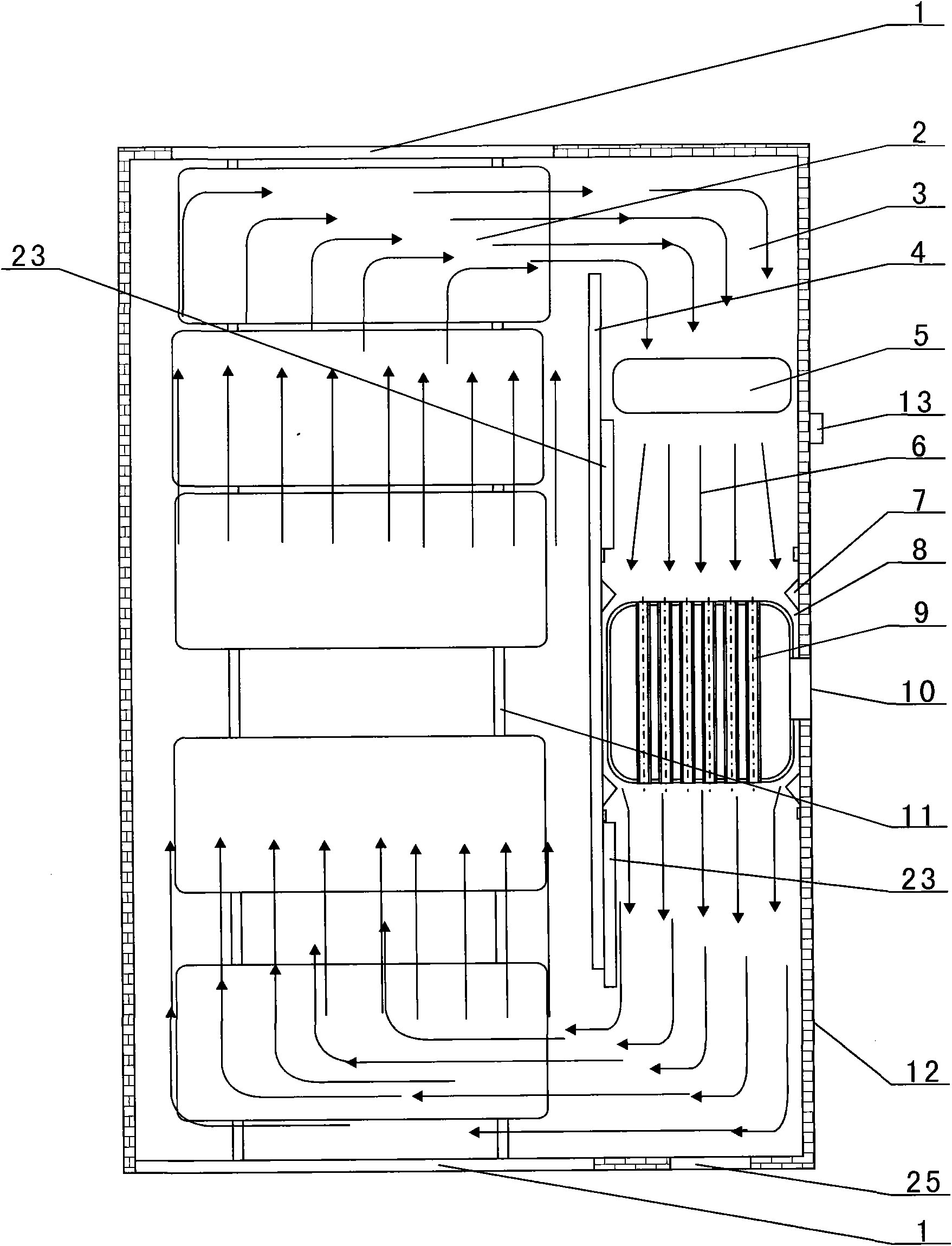
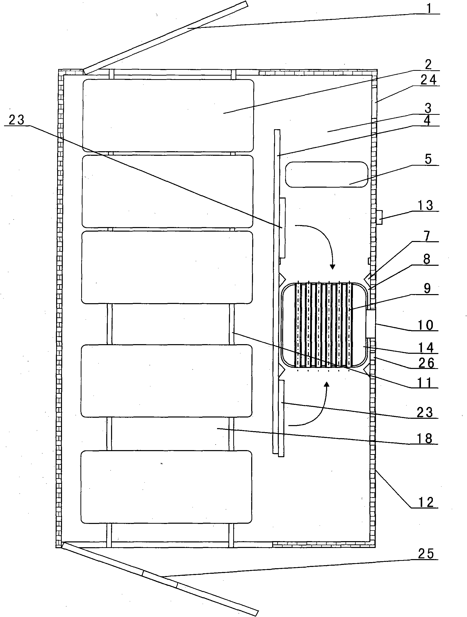
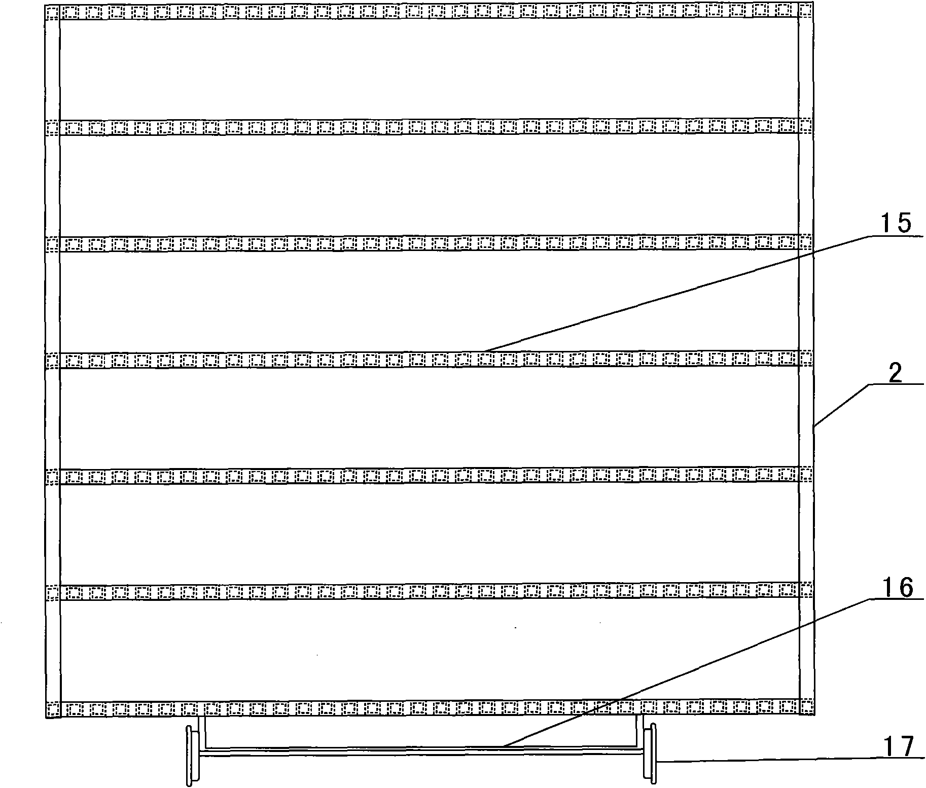
[0026] combined with Figure 1~4 The crop drying equipment described in includes a crop drying house 12, a retaining wall 4, a fan 5, a boiler 14, a drying rack and an exhaust system, the crop drying house 12 is a closed cavity, and the crop drying The middle part of the house 12 is provided with a retaining wall 4 connecting the roof of the crops drying house 12 and the ground of the crops drying house 12, the two ends of the retaining wall 4 and the walls of the crops drying house 12 are respectively spaced, and the retaining wall The distance between one end of the wall 4 forms an air inlet passage, and the distance between the other ends of the retaining wall 4 forms an air outlet ...


PUM


Abstract

The invention particularly relates to crop drying equipment which is characterized in that a retaining wall (4) is arranged in the middle in the a crop drying house (12) and is connected with the crop drying house (12), a spacing at one end of the retaining wall forms an air inlet passage, a spacing at the other end of the retaining wall forms an air outlet passage, a door (1) is arranged at the wall of one side of a drying room (18) of the crop drying house (12), and a plurality of drying racks are arranged in the drying room; a fan (5) is arranged at one side of the air inlet passage of an air duct (3) of the retaining wall, a boiler (14) is arranged at one side of the air outlet passage of the air duct of the retaining wall, and is provided with a plurality of heat pipes (9) through a boiler body, one ends of the heat pipes correspond to the fan (5), and an electric control system (13) is arranged at one side of the air outlet passage of the air duct (3). The crop drying equipment can fast dry crops, and realize the small fast drying of the crops by small environment formed by the crop drying house and the outside in a sealing manner.

Description

【Technical field】 [0001] The invention relates to a crop drying equipment, in particular to a room type crop drying equipment. 【Background technique】 [0002] It is well known that many crops and fruits and vegetables must be picked intensively during the full fruit period, but due to the short storage time of the crops and fruits and vegetables, the drying method must be used to increase the storage time; because the traditional drying method of fruits and vegetables takes a long time, the natural There are many air-drying and roasting, and some processes must use dehydrating agents, and the surface of the processed crops, fruits and vegetables will inevitably adhere to sand, which will affect later consumption. [0003] It can be seen from the above that grapes, wolfberry, chickpea, sand berries, sand dates, red dates, Chamgul, peppers, apricots, oil sunflowers, cotton bolls, fungus, shiitake mushrooms, persimmons, and various nuts and potatoes are in the drying process. ...

Claims


Application Information

Patent Timeline
IPC IPC(8): A23N12/08
Inventor 朱延根
Owner 朱延根
Learn More