
Method for manufacturing light-emitting diode lamp

A technology for light-emitting diodes and a manufacturing method, which is applied to semiconductor devices, light sources, point light sources, etc. of light-emitting elements, can solve the problems of occupying space, increasing costs, and consuming manpower, saving man-hours and costs, and reducing the space occupied. , the effect of increasing the heat dissipation efficiency

Inactive Publication Date: 2011-07-27
CATCHER TECH
View PDF0 Cites 2 Cited by
  • Summary
  • Abstract
  • Description
  • Claims
  • Application Information

AI Technical Summary

Problems solved by technology

[0006] Furthermore, in order to fix the light-emitting diode assembly on the heat pipe and heat dissipation fins, the prior art usually uses fasteners with complex structures.
Buckles not only increase the cost, but also take up space
In addition, assembling the buckle also consumes a considerable amount of manpower

Method used


Image

  • Method for manufacturing light-emitting diode lamp
  • Method for manufacturing light-emitting diode lamp
  • Method for manufacturing light-emitting diode lamp

Examples


Embodiment Construction

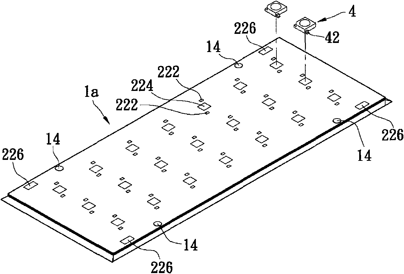
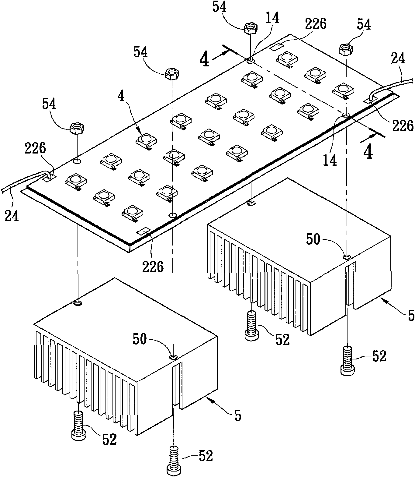
[0038] Please refer to figure 1 , is a schematic diagram of the manufacturing method of the light-emitting diode lamp of the present invention. The manufacturing method of the LED lamp of the present invention includes the following steps: firstly, at least one flat heat pipe 1a, 1b is provided, and a flat surface 12 is formed on each of them. The flat heat pipes 1a, 1b are preferably elongated plates. In this embodiment, since the flat heat pipe 1a and the flat heat pipe 1b are symmetrical, the following description will only take the flat heat pipe 1a as a representative.

[0039] The step of forming the flat surface 12 on the flat heat pipe 1a, 1b includes: firstly, polishing a plane of the flat heat pipe 1a, 1b; The flat surface 12 is for directly forming a printed circuit layer 2 on the flat heat pipes 1a, 1b.

[0040] Before forming the printed circuit layer 2, in order to fix the flat heat pipes 1a, 1b. The present invention provides a jig 30 on which the flat heat ...


PUM


Abstract

The invention discloses a method for manufacturing a light-emitting diode lamp. The method comprises the following steps of: providing at least one panel heat pipe, and forming one flat surface on each panel heat pipe; and providing a jig for fixing the panel heat pipes; forming a printed circuit layer. wherein the printed circuit layer can be divided into an insulation layer, an electric conduction layer and a solder mask layer; coating on the panel heat pipes sequentially; coating solder paste on the welding parts and placing a plurality of light-emitting diodes on the welding parts of the panel heat pipes; and allowing the panel heat pipes and the light-emitting diodes to pass through a reflow oven to produce the light-emitting diode lamp. The panel heat pipes can be further provided with a plurality of positioning holes which are used for positioning the jig and are matched with a simple assembly component to fix at least one heat dissipation fin module, so that the heat dissipation efficiency is improved, the manufacturing cost is saved and the occupied space is reduced.

Description

technical field [0001] The invention relates to a manufacturing method of a light-emitting diode lamp, in particular to a manufacturing method of directly welding a light-emitting diode assembly to a flat heat pipe. Background technique [0002] Light Emitting Diode (LED) has the advantages of small size, impact resistance, long life, low power consumption, cold light emission and no mercury pollution, etc., and has become the focus of research and development in the field of lighting recently. The development direction of light-emitting diodes is from small power to high power, with more diverse applications, from the earliest indicator lights to the current light-emitting diode lighting products. [0003] With the wide application of high-power light-emitting diodes, the demand for heat dissipation is gradually increasing. If the heat is not discharged in time, many problems will arise. For example, the luminous efficiency is reduced, the service life is shortened, the l...

Claims


Application Information

Patent Timeline
Patent Type & Authority Applications(China)
IPC IPC(8): F21V29/00F21V23/06F21Y101/02F21V29/508F21V29/51F21V29/76F21Y115/10
Inventor 邱世彬陈彦桦庄宜静
Owner CATCHER TECH
Learn More