Thyristor valve section and crimping method thereof

A thyristor valve and thyristor technology, which is applied in the direction of output power conversion devices, electrical components, electric solid devices, etc., can solve the problems that the center of the radiator cannot be guaranteed to be in the same straight line, the pressure of the thyristor is uneven, and the valve section is crimped unstable. Achieve the effect of providing reliability and stability, eliminating internal stress and improving electrical performance

Active Publication Date: 2011-07-27
XJ ELECTRIC +1
View PDF3 Cites 5 Cited by
  • Summary
  • Abstract
  • Description
  • Claims
  • Application Information

AI Technical Summary

Problems solved by technology

[0003] The object of the present invention is to provide a thyristor valve section and its crimping method to solve the problem that the existing thyristor valve section uses a tension spring to fix the radiator, and the center of the radiator cannot ensure the same straight line, resulting in uneven pressure of the thyristor, and the valve The internal stress generated by the rigid connection inside the segment is large, and the crimping instability of the valve segment is problematic

Method used


Image

  • Thyristor valve section and crimping method thereof
  • Thyristor valve section and crimping method thereof
  • Thyristor valve section and crimping method thereof

Examples


Embodiment Construction

[0019] 1. Thyristor valve section

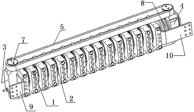
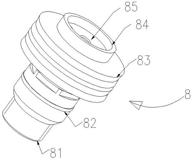
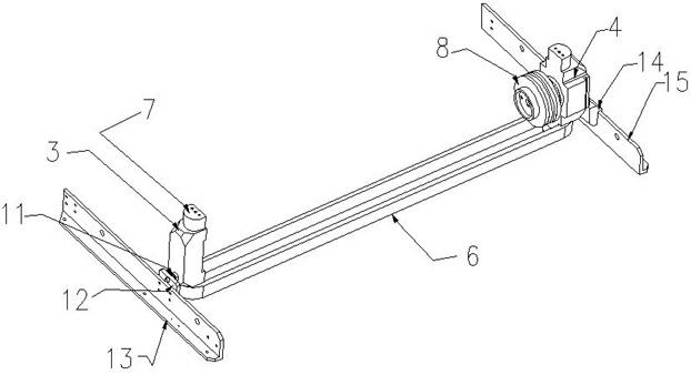
[0020] Thyristor valve section of the present invention such as figure 1 As shown, the valve section includes a valve group composed of alternately arranged water-cooled radiators 1 and thyristors 2 and a frame for installing the valve group. The upper and lower ends of the left end plate 3 and the right end plate 4 of the valve section are respectively provided with limit bolts 7, and the upper clamping ring 5 The two ends of the lower clamping ring 6 are clamped on the upper limit bolts of the left and right end plates of the valve section, and the two ends of the lower clamping ring 6 are clamped on the lower limit bolts of the left and right end plates of the valve section. Spring top pressure device 8, such as figure 2 As shown, the disc spring pressing device 8 is composed of a stainless steel bushing 81, a lock nut 82, a disc spring 83, a stainless steel retaining ring 84 and a stainless steel baffle 85, and the lock nut 82 is scre...


PUM


Abstract

The invention relates to a thyristor valve section and a crimping method thereof. The thyristor valve section comprises a valve group consisting of water cooling radiators and thyristors which are arranged alternately, wherein the left and right ends of the valve group are provided with a left end plate and a right end plate of the valve section respectively; the upper and lower end parts of the left and right end plates of the valve section are provided with a boss respectively, and an upper clamping ring and a lower clamping ring are sleeved on the bosses; the valve group is clamped between the upper clamping ring and the lower clamping ring; a disc spring top-pressing device is clamped at an end of the right end plate of the valve section in contact with the valve section; the water cooling radiators of the valve group of the thyristor valve section are directly mounted on the lower clamping ring so as to ensure that the centers of the water cooling radiators are collinear, thus ensuring uniform thyristor crimping force; and moreover, as the crimping force is provided for the valve section by the disc spring top-pressing device, the upper and lower clamping rings and the left and right end plates of the valve section together without involving a bolt, the crimping reliability and stability of the system are greatly improved.

Description

technical field [0001] The invention relates to a high-power power electronic rectification and inverter device, in particular to a thyristor valve section and a crimping method thereof. Background technique [0002] The Chinese patent specification published on December 2, 2009 with the application number 200910065332.7 discloses a series thyristor valve section connected by top pressure. The frame at one end of the frame is provided with an elastic clamping device, and the flange at the other end of the frame is provided with a pressing device, and a thyristor and a radiator arranged alternately are installed between the elastic clamping device and the pressing device. The valve group composed of top pressure connected series thyristor valve section is equipped with tension springs positioned and connected to the radiators on both sides of the fixed plate, and each radiator is respectively positioned and suspended on the frame through the tension springs. The central axis ...

Claims


Application Information

Patent Timeline
Patent Type & Authority Applications(China)
IPC IPC(8): H01L25/07H01L23/40H02M1/00H01L21/50
Inventor 姚为正张建肖晋马俊民朱新华李申李华君姚志国
Owner XJ ELECTRIC
Why Eureka
Try Eureka