Current mode converter with self-calibration output

A current mode, self-calibration technology, applied in the field of electronics, can solve the problems of inability to meet the requirements of the load regulation rate and low gain of the error amplifier, and achieve the effect of improving the load regulation rate and small fluctuations

Inactive Publication Date: 2012-07-18
UNIV OF ELECTRONICS SCI & TECH OF CHINA
View PDF0 Cites 0 Cited by
  • Summary
  • Abstract
  • Description
  • Claims
  • Application Information

AI Technical Summary

Problems solved by technology

[0004] The technical problem to be solved by the present invention is to propose a current mode converter with self-calibration output aiming at the problem that the error amplifier gain is low in the existing current mode converter and cannot meet the load regulation requirement

Method used


Image

  • Current mode converter with self-calibration output
  • Current mode converter with self-calibration output
  • Current mode converter with self-calibration output

Examples


Embodiment Construction

[0016] The technical solution of the present invention will be described in detail below in conjunction with the accompanying drawings and specific embodiments.

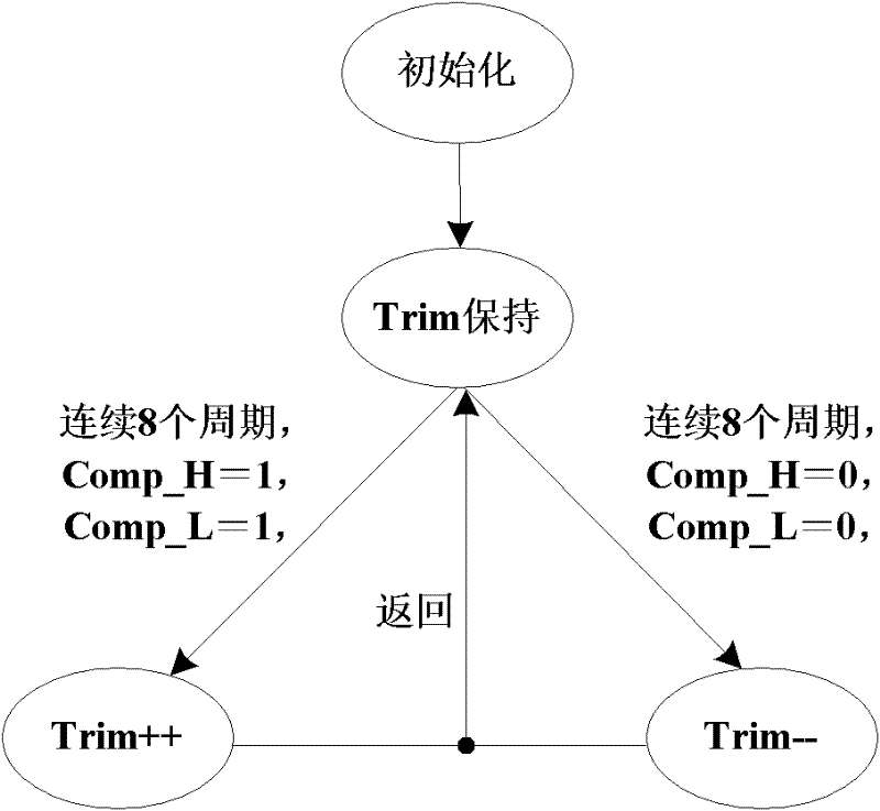
[0017] The invention performs digital self-adjustment on the traditional analog loop switching converter, reduces the dependence on technology, has strong portability, has simple self-adjustment principle, and well combines the advantages of digital circuits and analog circuits.

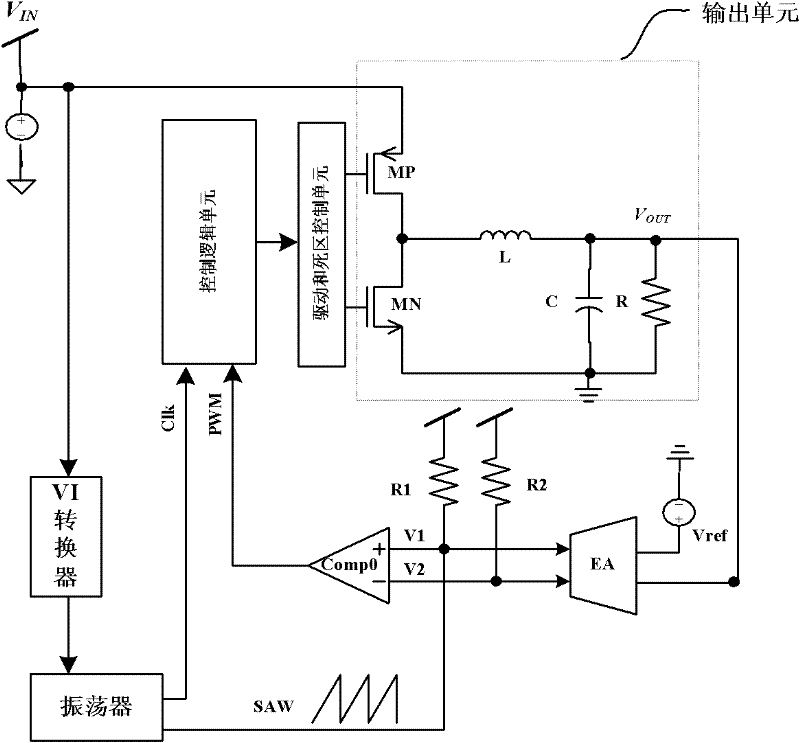
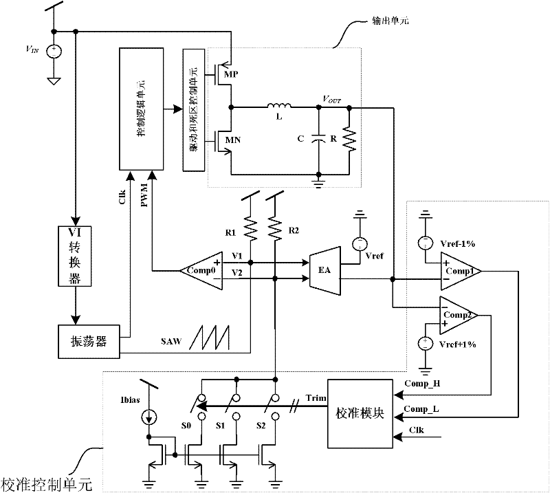
[0018] The present invention's current mode converter with self-calibrating output such as figure 2 As shown, it includes control logic unit, error amplifier EA, drive and dead zone control unit, first pull-up resistor R1, second pull-up resistor R2, PWM comparator Comp0 and output unit, the two inputs of the error amplifier EA The terminals are respectively connected to the output voltage Vout and the reference voltage Vref of the output unit, the output terminal of the error amplifier EA is a differential error voltage, the positive outp...


PUM


Abstract

The invention discloses a current mode converter with self-calibration output, which aims at solving the problems in the prior art that the gain of an error amplifier is reduced and cannot meet the requirement of load regulation rate. The current mode converter specifically comprises a control logic unit, an error amplifier, a driving and dead zone control unit, a first pull-up resistor, a secondpull-up resistor, a PWM (pulse width modulation) comparator and an output unit, and also comprises a digital calibration control unit, wherein the digital calibration control unit comprises a first comparator, a second comparator, a calibration module and a current mirror module. The current mode converter controls the change of current flowing through the second pull-up resistor connected on theerror amplifier through the digital calibration control unit, and further changes the error voltage by a stepping method so as to maintain a smaller fluctuation of the output voltage within a wider load range and improve the load regulation rate of the system.

Description

technical field [0001] The invention belongs to the field of electronic technology and relates to the design of a power converter used in power integrated circuits. Background technique [0002] Integrated power converters are widely used in various electronic products and are an important part of power integrated circuits. The step-down switching power converter in the power converter plays the role of transforming the battery voltage to a lower supply voltage in portable equipment, which can be divided into voltage mode and current mode control. The current mode control step-down switching power converter adopts double-loop control, and the inductor current and capacitor voltage of the switching converter are controlled separately as two control variables, so that the inductor current can be precisely controlled. [0003] The typical structure of the traditional step-down current mode control switching power converter is as follows: figure 1 As shown, it includes feedbac...

Claims


Application Information

Patent Timeline
Patent Type & Authority Patents(China)
IPC IPC(8): H02M3/157H02M3/158
Inventor 罗萍甄少伟李江昆祝晓辉杨康
Owner UNIV OF ELECTRONICS SCI & TECH OF CHINA
Why Eureka
Try Eureka