Double-cavity thermal field of crystal silicon ingot casting furnace and control method thereof

A control method and ingot furnace technology, applied in chemical instruments and methods, single crystal growth, crystal growth, etc., can solve the problem that the solid-liquid interface cannot be continuously corrected, the crystal melting and crystal growth process time cannot be taken into account, and the crystal growth is controllable Insufficient performance and other problems, to achieve the effect of increasing process time and power consumption, easy installation and use, and increasing temperature gradient

Inactive Publication Date: 2011-08-03
ZHEJIANG JINGGONG SCI & TECH
View PDF7 Cites 13 Cited by
  • Summary
  • Abstract
  • Description
  • Claims
  • Application Information

AI Technical Summary

Problems solved by technology

[0008] At present, all ingot casting furnaces are designed with a fixed hot chamber. In the actual production process, there is a disadvantage that the process time of crystal melting and crystal growth cannot be taken into account. At the same time, once the thermal field components are installed, only a fixed solid-liquid interface can be used, which cannot be used in the process. During the growth process, the solid-liquid interface is constantly corrected, and the controllability of crystal growth is not strong

Method used


Image

  • Double-cavity thermal field of crystal silicon ingot casting furnace and control method thereof
  • Double-cavity thermal field of crystal silicon ingot casting furnace and control method thereof
  • Double-cavity thermal field of crystal silicon ingot casting furnace and control method thereof

Examples


Embodiment Construction

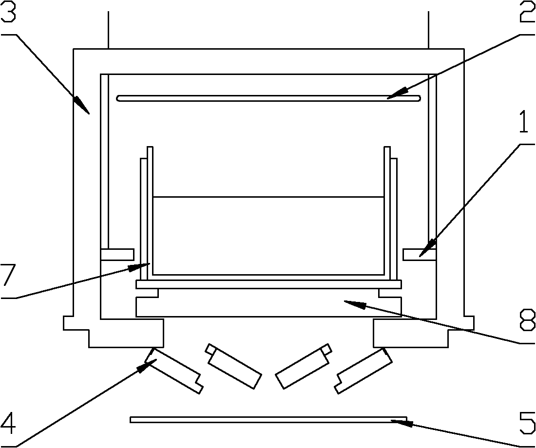
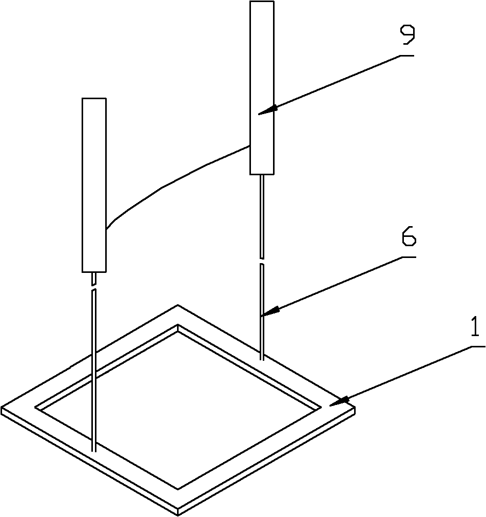
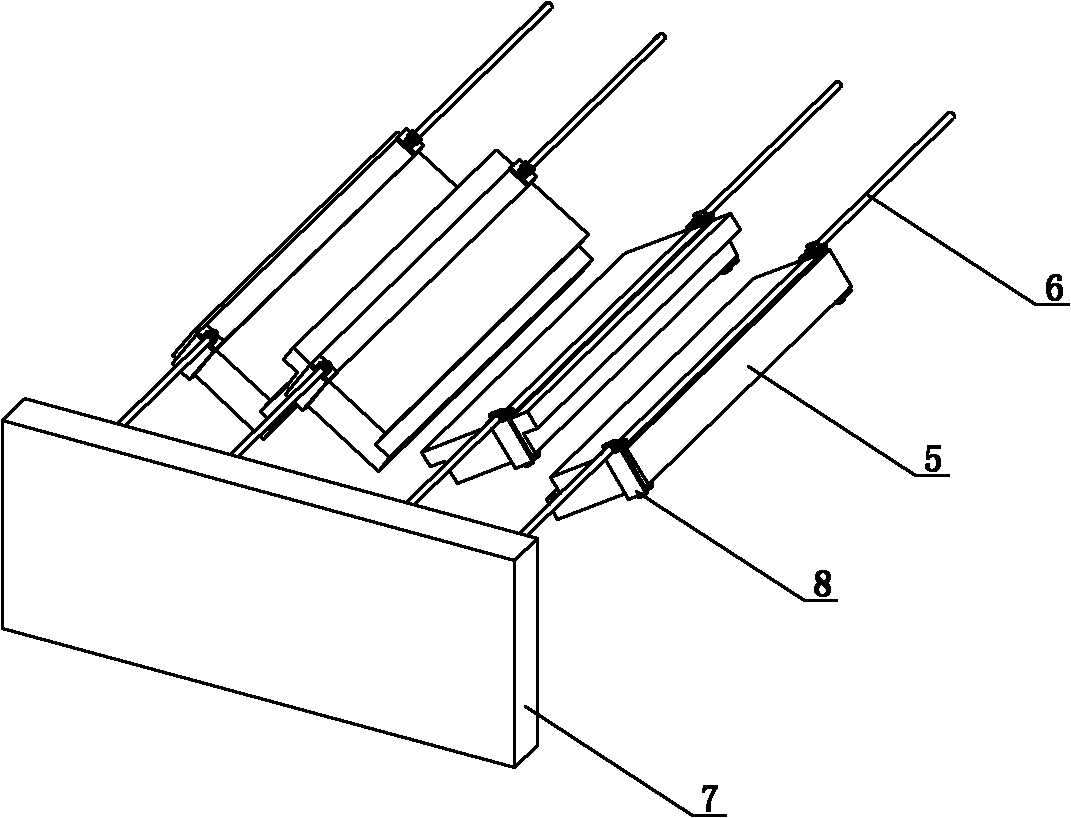
[0030] Such as figure 1 The shown double-chamber thermal field of a crystalline silicon ingot casting furnace consists of a thermal insulation cage 3, a single upper heater 2 arranged in the thermal insulation cage, a heat exchange table 8 for placing a crucible 7, and a heat exchange table and a heat insulation cage. The heat dissipation between the outside of the cage is composed of a water-cooled plate 5 under the heat-insulating cage, and a heat-exchanging platform 8 is placed in the heat-insulating cage 3. The inner wall of the heat-insulating cage 3 is provided with a circle of friction on it and can be moved along the The dividing plate 1 of its lifting. The partition is made of heat insulating material. The partition 1 is located between the inner wall of the heat insulation cage and the outer wall of the heat exchange platform. Suspenders 6 are fixed on the partitions on both sides of the heat exchange platform. The upper ends of the suspension rods pass through the h...


PUM


Abstract

The invention discloses a double-cavity thermal field of a crystal silicon ingot casting furnace and a control method thereof. All traditional ingot casting furnaces adopt the design of a fixed thermal cavity, and have the defects that the crystal melting process time and the crystal growing time can not be taken into account simultaneously in the practical production process; in addition, after the thermal field part is installed, only a fixed solid-liquid interface can be used, the solid-liquid interface can not be modified in the growing process, and the growing controllability of crystalsis not high. The double-cavity thermal field is characterized in that a circle of insulating clapboards which support against the inner wall of an insulating cage and can lift up and down along the inner wall are arranged on the inner wall of the insulating cage, the insulating clapboards are made of insulating materials and positioned between the inner wall of the insulating cage and the outer wall of a heat exchanging table, the insulating clapboards positioned at two sides of the heat exchanging table are respectively fixedly connected with lifting rods, and the upper ends of the lifting rods penetrate through the insulating cage and are connected with a lifting driving mechanism. The double-cavity thermal field modifies the solid-liquid interface and the temperature gradient of the solid at any time through the lifting insulating clapboards, thus the optimal crystal growing environment and control on the shape of the solid-liquid interface are realized.

Description

technical field [0001] The invention relates to the thermal field field of a crystalline silicon ingot furnace, in particular to a double-chamber thermal field of a crystalline silicon ingot furnace and a control method thereof. Background technique [0002] After years of development, polysilicon ingot casting technology has been widely recognized by the photovoltaic industry due to its low-consumption, high-efficiency, fully automatic production methods and continuous improvement in the quality of finished products. [0003] There are many factors that affect the efficiency of solar cells. For the current solar cell industry, even an increase of 0.1 percentage point in cell conversion efficiency is a very meaningful technical improvement. High-quality battery silicon wafers have very high requirements on the size, uniformity, morphology and structure of grains, and the content of impurities in grain boundaries, although these requirements can be more or less explored and i...

Claims


Application Information

Patent Timeline
Patent Type & Authority Applications(China)
IPC IPC(8): C30B11/00C30B29/06C30B28/06
Inventor 王琤徐芳华赵波高杰朱志钿王明明任晓坜高波
Owner ZHEJIANG JINGGONG SCI & TECH
Why Eureka
Try Eureka