

Automatic racking device for drill rod
A technology of automatic discharge and drill pipe, applied in the direction of drill pipe, drill pipe, drilling equipment, etc., can solve the problems of low work efficiency, high labor intensity of workers, high risk, reduce labor intensity, enhance safety and reliability, mechanization high degree of effect
- Summary
- Abstract
- Description
- Claims
- Application Information
AI Technical Summary
Problems solved by technology
Method used
Image

Examples
Embodiment Construction
[0033] The present invention will be described in further detail below in conjunction with the accompanying drawings.
[0034] The present invention includes a support frame 2 , a drill pipe horizontal conveying mechanism 1 , a drill pipe transfer mechanism 6 , a rathole clamp hand 3 , a hydraulic tong 5 , a vertical root lifting mechanism 7 and a vertical root discharge mechanism 9 .
[0035] The drill pipe horizontal conveying mechanism 1 is used for conveying the drill pipe on the ground to the bottom of the supporting frame 2 .
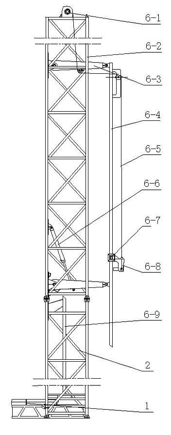
[0036] The drill pipe transfer mechanism 6 is used for lifting and horizontal transfer of the drill pipe; it is installed on the lower part of the support frame. Specifically, the drill rod transfer mechanism includes a fixed guide rail 6-9, a vertical guide rail 6-4, a support arm 6-3, a hydraulic cylinder A6-6, and a sliding trolley 6-7; the fixed guide rail 6-9 is vertical It is arranged and fixed on the bottom of the support frame 2; the vert...
PUM
 Abstract
Description
Claims
Application Information