Method for on board diagnostics and system for on board diagnostics

An on-board diagnosis and vehicle technology, which is applied in the system field of on-board diagnosis methods, can solve problems such as difficult to find out the relationship between boosted air pressure, and achieve the effect of simplifying on-board diagnosis and easy development

Inactive Publication Date: 2011-08-03
VOLVO LASTVAGNAR AB
View PDF6 Cites 7 Cited by
  • Summary
  • Abstract
  • Description
  • Claims
  • Application Information

AI Technical Summary

Problems solved by technology

It is also very difficult to find the relationship between charge air pressure and these variables

Method used


Image

  • Method for on board diagnostics and system for on board diagnostics
  • Method for on board diagnostics and system for on board diagnostics
  • Method for on board diagnostics and system for on board diagnostics

Examples


Embodiment Construction

[0026] In the drawings, the same or similar elements are denoted by the same reference numerals. The drawings are merely schematic representations, not intended to portray specific parameters of the invention. Moreover, the drawings are intended to depict only typical embodiments of the invention, and therefore should not be considered as limiting the scope of the invention.

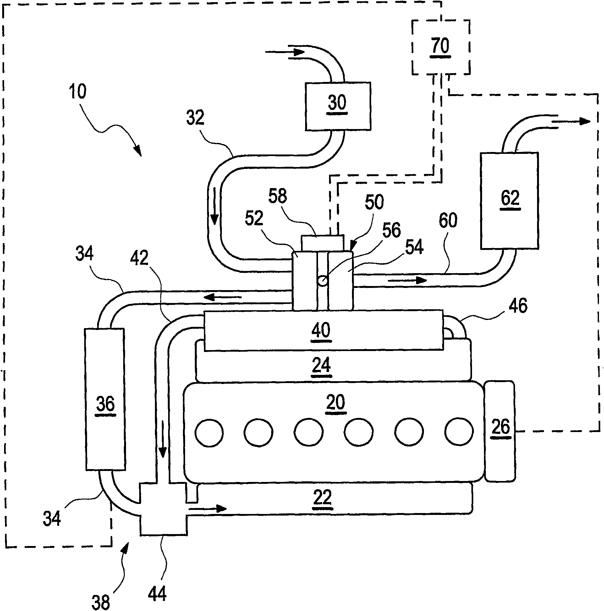
[0027] figure 1 Engine 20 of a vehicle (not shown) equipped with a turbocharger 50 including a variable geometry turbine 54 is depicted. Air is supplied to intake manifold 22 of engine 20 through air tubes 32 and 34 . The air pipe 32 is equipped with an air filter 30 . A compressor 52 of a turbocharger 50 is arranged between the air line 32 and the air line 34 . A charge air cooler 36 is arranged in the air duct 34 . Compressed air is supplied into intake manifold 22 through charge air cooler 36 in air duct 34 .

[0028]The engine 20 is equipped, for example, with an EGR system in which exhaust gas...


PUM


Abstract

The invention relates to a method for on board diagnostics for detecting a charge air leakage in a vehicle, wherein air is compressed by a turbine (50) with variable geometry and fed to the combustion engine (20). The steps are performed of feeding compressed air to the engine (20) without fuel supply to the engine (20); estimating a boost pressure from a current vane geometry of the variable geometry turbine (54); measure the actual boost pressure (104); and comparing the estimated boost pressure with the measured boost pressure (104).

Description

technical field [0001] The invention relates to an on-board diagnostic method and a system for an on-board diagnostic method according to the preambles of the independent claims. Background technique [0002] It is known that statutory and aftermarket demands drive the development of more advanced on-board diagnostics (OBD) to detect malfunctioning devices in vehicles. [0003] In order to detect charge air leaks in the charge air system of an internal combustion engine, it is known in the prior art to compare simulated values ​​such as the intake manifold pressure with measured values. If this measured value is lower than the simulated value, a leak has been detected. Its model can be based on several known variables, such as engine speed and / or turbine speed, engine torque, injected fuel quantity, actuator position of the variable geometry turbine, advance angle, needle opening pressure of the injector. Usually, the advance angle and the needle opening pressure of the in...

Claims


Application Information

Patent Timeline
Patent Type & Authority Applications(China)
IPC IPC(8): F02D41/00F02D9/06G01M3/02F02D41/12G01M17/007B60W10/06F02B37/12
CPCF02B37/22F02B39/16F02D41/0007F02D2200/0406F02M25/0722Y02T10/144F02M25/0726F02D41/221G01M15/14G01M15/09F02M25/0707F02D2200/0408Y02T10/40F02D2200/0402F02M26/05F02M26/19F02M26/22Y02T10/12
Inventor 斯特凡·威克纳
Owner VOLVO LASTVAGNAR AB
Why Eureka
Try Eureka