
Twist drill with changeable helical angles

A technology of helix angle and twist drill, which is applied in the field of metal cutting tools, can solve the problems of difficulty in taking into account chip removal and cutting, the service life of the drill bit is reduced, and the cutting edge machinability is poor, so as to improve processing stability, reduce cutting heat, drill Sharpening effect

Inactive Publication Date: 2011-08-10
江苏飞达钻头股份有限公司
View PDF5 Cites 4 Cited by
  • Summary
  • Abstract
  • Description
  • Claims
  • Application Information

AI Technical Summary

Problems solved by technology

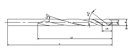
[0002] A standard twist drill is composed of a shank and a working section. The working section is provided with a double helix groove, and the helix angle of the helical groove is a fixed value. If the helix angle is too large, it will be difficult to remove chips when the helix angle is too small. The machinability of the cutting edge is poor. The helix angle of the existing standard twist drill is usually about 30°, which makes it difficult to balance chip removal and cutting, which will eventually lead to a decrease in the service life of the drill bit.

Method used


Image

  • Twist drill with changeable helical angles
  • Twist drill with changeable helical angles
  • Twist drill with changeable helical angles

Examples


Embodiment 1

[0017] Use the same production batch of W6Mo5Cr4V2, Ф10.80 high-speed steel bars to produce Ф10 specification twist drills A and B (the heat treatment process of both is the same), A sample is the existing standard twist drill, B sample is the present invention Twist drill, the specific parameters are as follows:

[0018] Sample A: total length L=133mm, working section length L1=87mm, working section helix angle 30°, diameter d=10mm, drill tip core thickness 1.6mm, chisel edge rake angle γ=-52°;

[0019] Sample B: total length L=133mm, working section length L1=87mm, working section front section length L2=15mm, front section helix angle ω1=37°, back section helix angle ω2=16°, diameter d=10mm, near the drill tip step The small diameter d1=6.8mm, the core thickness of the drill point is 0.15mm, and the chisel edge rake angle γ=5°.

[0020] Test method: TK7640 CNC vertical boring and milling machine, cutting speed: 28m / min, feed rate 0.25mm / r, drilling depth 30mm. Cutting tes...

Embodiment 2

[0026] Use the same production batch of W9Mo3Cr4V, Ф6.6 high-speed steel bars to produce Ф6.0 specification straight shank twist drill samples A and B (same heat treatment process), sample A is the existing standard twist drill, sample B is based The twist drill invented, the specific parameters are as follows:

[0027] Sample A: total length L=101mm, working section length L1=63mm, working section helix angle 30°, diameter d=6mm, drill tip core thickness 1.05mm, chisel edge rake angle γ=-53°;

[0028] Sample B: total length L=101mm, length of working section L1=63mm, length of front section of working section L2=10mm, helix angle of front section ω1=36°, helix angle of back section ω2=16°, diameter d=6mm, near the drill tip step The small diameter d1=4.2mm, the core thickness of the drill point is 0.12mm, and the chisel edge rake angle γ=4°.

[0029] Test method: TK7640 CNC vertical boring and milling machine, cutting speed: 28m / min, feed rate 0.17mm / r, drilling depth 20mm. ...


PUM


Abstract

The invention relates to a twist drill with changeable helical angles, belonging to a metal cutting tool technology. The twist drill comprises a handle part and a working segment, wherein the working segment is provided with a double-helical groove divided into a front segment near a drill point and a rear segment near the handle part, the helical angle of the front segment is 35-38 DEG, the helical angle of the rear segment is 15-17 DEG, and the front segment and the rear segment are in smooth transition. The twist drill provided by the invention better gives consideration to cutting and chip removing processes, and has the advantages of long service life, stability in drilling and high drilling quality.

Description

technical field [0001] The invention belongs to the technology of metal cutting tools, and relates to a twist drill with variable helix angle. Background technique [0002] A standard twist drill is composed of a shank and a working section. The working section is provided with a double helix groove, and the helix angle of the helical groove is a fixed value. If the helix angle is too large, it will be difficult to remove chips when the helix angle is too small. Then the machinability of the cutting edge is poor, and the helix angle of the existing standard twist drill is usually about 30°, which makes it difficult to balance chip removal and cutting, which will eventually lead to a decrease in the service life of the drill bit. Contents of the invention [0003] The technical problem to be solved by the present invention is to provide a twist drill with variable helix angle, which has good cutting and chip removal, long service life, stable drilling and high drilling qual...

Claims


Application Information

Patent Timeline
IPC IPC(8): B23B51/02
Inventor 张建华
Owner 江苏飞达钻头股份有限公司
Learn More