
High-power solar energy concentrated photovoltaic system based on Cassegrain structure

A solar concentrating and photovoltaic system technology, applied in the direction of condensing mirror, photovoltaic module, photovoltaic power generation, etc., can solve the problems of low utilization rate of solar energy, inability to achieve full-time work, large aspect ratio, etc., achieve low-cost photovoltaic power generation, solve energy problems Crisis, effect of high energy flux density

Inactive Publication Date: 2011-08-10
CHANGCHUN INST OF OPTICS FINE MECHANICS & PHYSICS CHINESE ACAD OF SCI
View PDF4 Cites 17 Cited by
  • Summary
  • Abstract
  • Description
  • Claims
  • Application Information

AI Technical Summary

Problems solved by technology

The patent with publication date of June 11, 2008 and publication number CN201072857Y discloses a compound parabolic reflective concentrating solar power generation panel. This concentrating reflector is composed of a substrate with a compound parabolic smooth concave surface and a reflective film. , it does not rely on the solar tracking system, which reduces the cost of use, but because the inclination angle changes greatly when the sun shines on the ground, the device cannot work full-time, and the solar energy utilization rate is low. In addition, the device has an aspect ratio Disadvantages of large size, bulky structure and low concentration ratio
The patent whose publication date is June 2, 2010 and whose publication number is CN101719738A discloses a high-efficiency solar concentrating photovoltaic system. The optical concentrating mirror part of this system is composed of a concentrating mirror and a uniform beam inserted in the central hole of the concentrating mirror. Although this system has the advantage of high light-gathering ratio, the upper and lower surfaces of its condenser lens are all high-order aspheric surfaces, which will face great difficulties in the process.

Method used


Image

  • High-power solar energy concentrated photovoltaic system based on Cassegrain structure
  • High-power solar energy concentrated photovoltaic system based on Cassegrain structure
  • High-power solar energy concentrated photovoltaic system based on Cassegrain structure

Examples


Embodiment Construction

[0012] The present invention will be described in further detail below in conjunction with the accompanying drawings and specific embodiments.

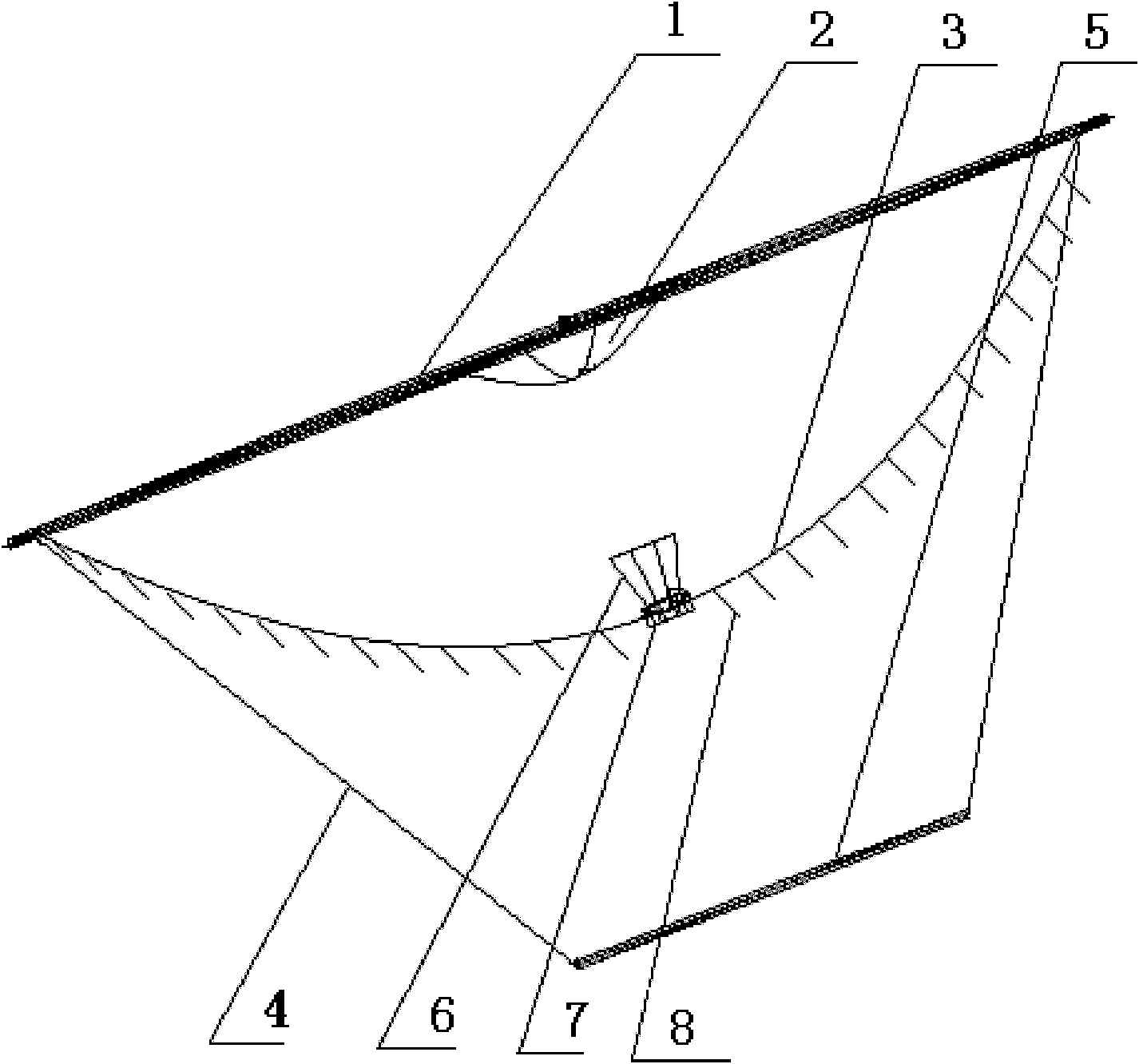
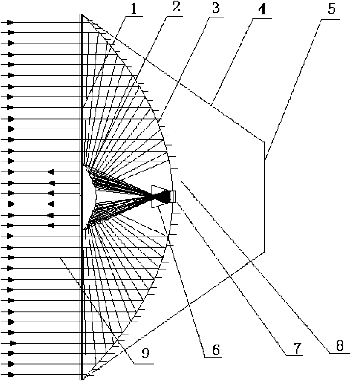
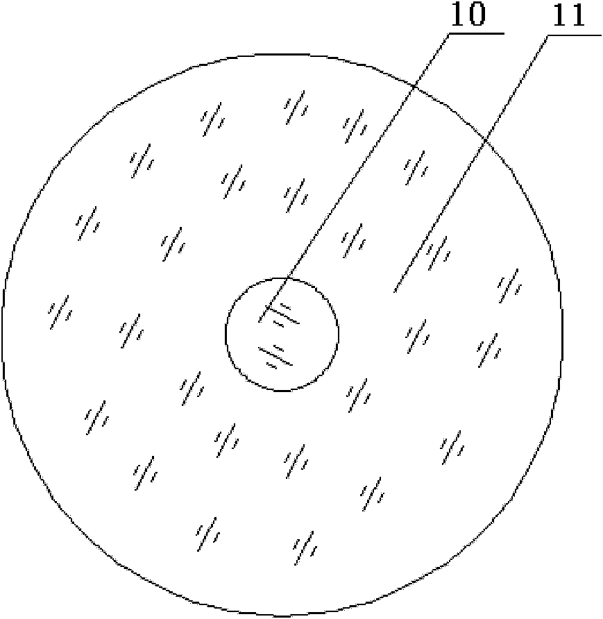
[0013] Such as Figure 1 to Figure 3 As shown, the present invention is based on a Cassegrain structure high-power concentrated solar photovoltaic system, including a flat glass cover plate 1, a hyperbolic convex secondary reflector 2, a parabolic concave primary reflector 3, a support structure 4, a base 5, and a light uniform column 6 And the solar cell 7, the flat glass cover plate 1 is arranged on the port plane of the parabolic concave main reflector 3 towards the sun; the hyperbolic convex secondary reflector 2 is fixed on the flat glass cover plate 1, and the parabolic concave main reflector 3 passes through the supporting structure 4 is fixed on the base 5; the focal point of the parabolic concave primary reflector 3 is located at the center point of its own reflector port plane, one focal point of the hyperbolic convex second...


PUM


Abstract

The invention discloses a high-power solar energy concentrated photovoltaic system based on a Cassegrain structure, which belongs to the technical field of solar energy photovoltaic generating application. The system comprises a plain glass cover board, a hyperbolic convex secondary reflector, a parabolic concave primary reflector, a supporting structure, a base, a dodging column and a solar battery; the base is fixed on a two-dimensional solar-tracking system to realize solar tracking in real time; the parabolic concave primary reflector is confocal with the hyperbolic convex secondary reflector; a light ray meets a total reflection condition when passing through walls of the dodging column; and the dodging column can be used for uniformly coupling a sun ray converged by the parabolic concave primary reflector and the hyperbolic convex secondary reflector onto the working surface of the solar battery. The high-power solar energy concentrated photovoltaic system can be used for converting the solar energy into electric energy with high efficiency and low cost so as to realize environmentally-friendly and sustainable use of the energy source.

Description

technical field [0001] The invention belongs to the application field of solar photovoltaic power generation technology, and specifically relates to a high-power solar concentrated photovoltaic system based on a Cassegrain structure. Background technique [0002] The limitation of fossil energy reserves is one of the main factors for the development of renewable energy. Renewable energy represented by solar energy has become an important alternative energy source for energy diversification and sustainable development. At present, solar energy has been widely used in the fields of heating and power generation. The total solar radiation energy received by the earth's surface is huge, but the radiation energy flow density is very low. In order to obtain greater energy, the light energy receiving area must be increased. One of the easiest ways to increase the light receiving area is to splice large-area solar cells, but this method will consume a large amount of expensive solar...

Claims


Application Information

Patent Timeline
IPC IPC(8): H02N6/00G02B19/00G02B7/182G02B27/09H02S40/22
CPCY02E10/52
Inventor 张来明潘其坤谢冀江阮鹏李殿军
Owner CHANGCHUN INST OF OPTICS FINE MECHANICS & PHYSICS CHINESE ACAD OF SCI
Learn More