Check patentability & draft patents in minutes with Patsnap Eureka AI!

Methods and systems for reducing piping vibration

A piping, vibration-responsive technology used in combustion methods, machines/engines, lighting and heating equipment to address issues such as feeder injector fatigue failures

Inactive Publication Date: 2011-08-10
GENERAL ELECTRIC CO
View PDF6 Cites 2 Cited by
  • Summary
  • Abstract
  • Description
  • Claims
  • Application Information

AI Technical Summary

Problems solved by technology

Vibration tends to cause fatigue failure of components of the feed injector

Method used


Image

  • Methods and systems for reducing piping vibration
  • Methods and systems for reducing piping vibration
  • Methods and systems for reducing piping vibration

Examples


Embodiment Construction

[0012] The following detailed description illustrates the present disclosure by way of example and not limitation. This description clearly enables one skilled in the art to make and use the disclosure, describes several embodiments, adaptations, variations, alternatives and uses of the disclosure, including what is presently believed to be the best way of carrying out the disclosure. pattern stuff. The present disclosure is described as applied to a preferred embodiment, namely, a system and method of injecting feedstock into a reactor. However, it is contemplated that this disclosure has general application to piping systems in industrial, commercial, and residential applications.

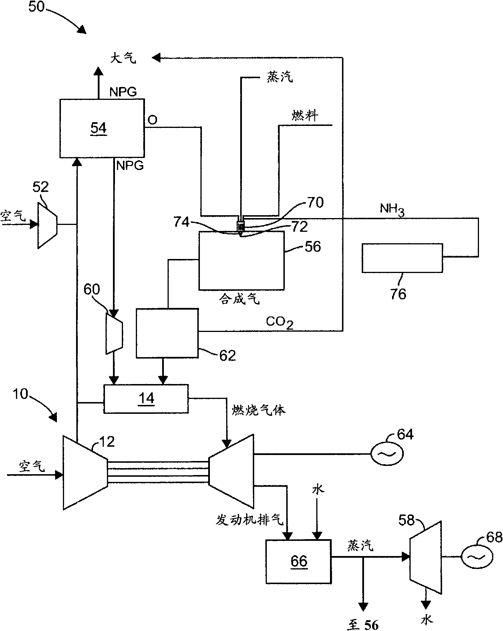
[0013] figure 1 is a schematic diagram of an exemplary integrated gasification combined cycle (IGCC) power generation system 50 . The IGCC system 50 generally includes a main air compressor 52, an air separation unit 54 coupled in flow communication with the compressor 52, a gasifier 56 couple...


PUM


Abstract

Methods and systems for a gasifier system are provided. The gasifier system includes a first substantially cylindrically shaped conduit that includes a radially inner surface, a second conduit at least partially within and substantially concentrically aligned with the first conduit, and at least one support member extending between a radially outer surface of the second conduit and the radially inner surface of the first conduit wherein the support member is positioned along a length of the second conduit to facilitate reducing a vibratory response of at least one of the first and second conduits to a flow of fluid through at least one of the first and second conduits.

Description

technical field [0001] The present invention relates generally to integrated gasification combined cycle (IGCC) power generation systems, and more particularly to advanced methods and apparatus for injecting feedstock into gasifiers. Background technique [0002] At least some known gasifiers convert a mixture of fuel, air or oxygen, steam and / or lime into an output of partially oxidized gas, sometimes referred to as "syngas". The syngas is supplied to the combustors of gas turbine engines that drive generators that supply electrical power to the grid. Exhaust gas from the gas turbine engine may be supplied to a heat recovery steam generator that generates steam for driving the steam turbine. The power generated by the steam turbine also drives a generator that supplies electrical power to the grid. [0003] Fuel, air or oxygen, steam and / or lime are injected into the gasifier from separate sources through feed injectors that couple the feed sources to the feed nozzles. A...

Claims


Application Information

Patent Timeline
Patent Type & Authority Applications(China)
IPC IPC(8): F23D1/00F23D11/38F23G5/027F23G7/00
CPCC10J2200/152F23G2206/203Y02E20/18F23G2209/101C10J2200/09Y02E20/12C10J2300/1223C10J3/845C10K1/101C10J3/506F23G2201/40C10J3/84F23G2209/102F01K23/067F23G2206/202Y10T29/49345
Inventor C·Y·郭
Owner GENERAL ELECTRIC CO
Features
  • R&D
  • Intellectual Property
  • Life Sciences
  • Materials
  • Tech Scout
  • Unparalleled Data Quality
  • Higher Quality Content
  • 60% Fewer Hallucinations
Learn More