Device and method for measuring voltage of noncontact charge induced high-voltage transmission line

A high-voltage transmission line and charge induction technology, applied in the field of electronic sensors, can solve the problems of inability to automatically provide digital signals in transmission and distribution systems, small static and dynamic accuracy ranges, and low integration and digitization, so as to improve reliability and work. Efficiency, reduced energy consumption, and ease of grid construction and maintenance

Inactive Publication Date: 2011-08-17
STATE GRID SHANDONG ELECTRIC POWER
View PDF4 Cites 37 Cited by
  • Summary
  • Abstract
  • Description
  • Claims
  • Application Information

AI Technical Summary

Problems solved by technology

With the continuous increase of grid voltage, the volume of traditional transformers is getting larger and larger, the insulation structure is becoming more and more complex, and the difficulty of manufacturing is also increasing.
At the same time, problems such as hysteresis, magnetic saturation, secondary non-open circuit, low linearity, and small static and dynamic accuracy ranges in traditional transformers have become increasingly prominent, which can no longer provide guarantee for the development of power systems.
Since the output of the traditional transformer is an

Method used


Image

  • Device and method for measuring voltage of noncontact charge induced high-voltage transmission line
  • Device and method for measuring voltage of noncontact charge induced high-voltage transmission line
  • Device and method for measuring voltage of noncontact charge induced high-voltage transmission line

Examples


Embodiment Construction

[0052] The preferred embodiments of the present invention will be described in detail below in conjunction with the accompanying drawings; it should be understood that the preferred embodiments are only for illustrating the present invention, rather than limiting the protection scope of the present invention.

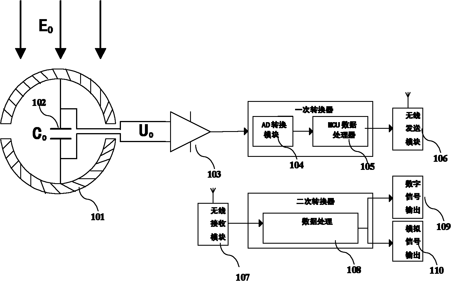
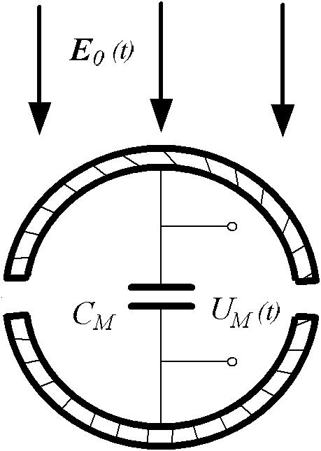
[0053] figure 1 The internal structure diagram of the unipolar voltage sensor; as shown in the figure, as shown in the figure, the non-contact charge induction type high-voltage transmission line voltage measuring device provided by the present invention includes a voltage test sensor, and the voltage test sensor includes an electric field sensor 101. A data processing module and a signal output module;

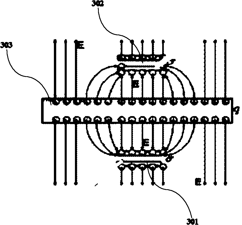
[0054] The electric field sensor collects the electric field signal around the transmission line 303, and transmits the electric field signal to the data processing module;

[0055] The data processing module converts the received electric field signal into a voltage ...


PUM


Abstract

The invention discloses a device and a method for measuring voltage of a noncontact charge induced high-voltage transmission line, and relates to an electronic sensor in the field of intelligent power grids. The device comprises a voltage testing sensor; the voltage testing sensor comprises an electric field sensor, a voltage correcting sensor, a data processing module and a signal output module, wherein the electric field sensor is used for acquiring electric field signals around the transmission line, the data processing module is used for receiving the electric field signals and converting the electric field signals into voltage signals, and the signal output module is used for receiving the voltage signals, processing the voltage signals and outputting the processed voltage signals to a display; and the electric field sensor comprises two hemispherical shell types electrodes and a measurement capacitor placed in a cavity formed by two hemispherical shells, and two polar plates of the measurement capacitor are connected with the hemispherical shell types electrodes respectively. Because the acquired signals are digitally transmitted, the precision is improved, the measuring range is wide, and saturation is not caused; and because the sensors are single-pole noncontact sensors, the installation is simple, the detachment is convenient, the volume is small, and great convenience is brought to construction and maintenance of the power grids.

Description

technical field [0001] The invention relates to electronic sensors in the field of smart grids, in particular to an active electronic unipolar voltage sensor and a voltage measurement method. Background technique [0002] The development of modern power system is characterized by large capacity, high voltage, miniaturization, digitization and automation of transmission and distribution systems. With the continuous increase of grid voltage, the volume of traditional transformers is getting larger and larger, the insulation structure is becoming more and more complex, and the difficulty of manufacturing is also increasing. At the same time, problems such as hysteresis, magnetic saturation, secondary non-open circuit, low linearity, and small static and dynamic accuracy ranges in traditional transformers have become increasingly prominent, which can no longer provide guarantee for the development of power systems. Since the output of the traditional transformer is an analog si...

Claims


Application Information

Patent Timeline
IPC IPC(8): G01R19/25
Inventor 汪金刚何为魏钢王平刘聪汉
Owner STATE GRID SHANDONG ELECTRIC POWER
Why Eureka
Try Eureka