Device and method for laying fibers

A technology for laying devices and optical fibers, which is applied in the direction of optical fiber/cable installation, measuring devices, instruments, etc. It can solve the problems of low construction efficiency, slow optical fiber speed, and unsightly appearance, and achieve the effects of improving construction efficiency, easy processing, and beautiful appearance

Inactive Publication Date: 2013-09-04
FOCUSED PHOTONICS
View PDF0 Cites 0 Cited by
  • Summary
  • Abstract
  • Description
  • Claims
  • Application Information

AI Technical Summary

Problems solved by technology

[0007] However, when the tape is laid on site, only the staff manually stick the tape on the optical fiber. The speed of the tape to cover the optical fiber is slow, and the construction efficiency is low; and it is not beautiful after laying

Method used


Image

  • Device and method for laying fibers
  • Device and method for laying fibers
  • Device and method for laying fibers

Examples


Embodiment 1

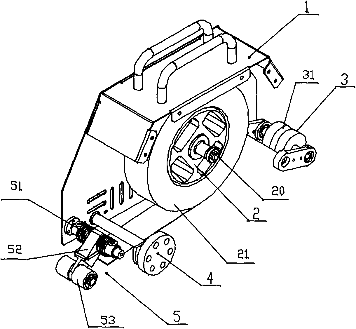
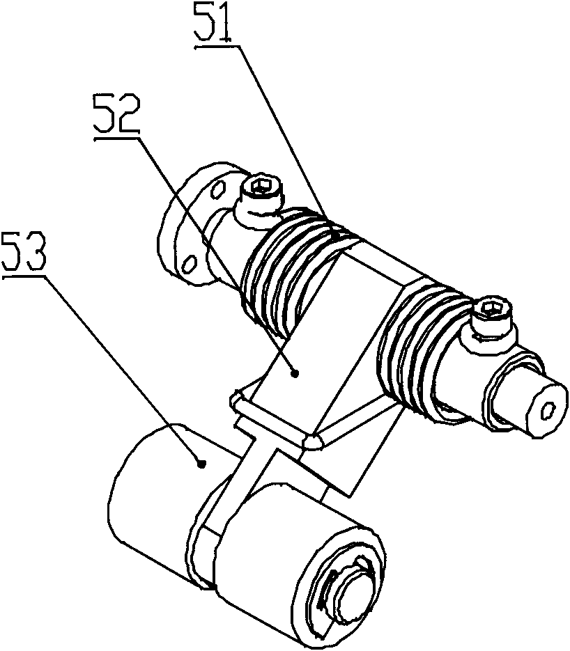
[0042] see figure 1 , figure 2 , an optical fiber laying device, comprising a housing 1, a gluing module 2, a limiting module 3, and a pressing module 5;

[0043] The gluing module 2, the limiting module 3, and the pressing module 5 are all installed on the housing 1;

[0044] The gluing module 2 rotates around its central axis 20 and is used to install the tape roll 21 and apply the tape to cover the optical fiber.

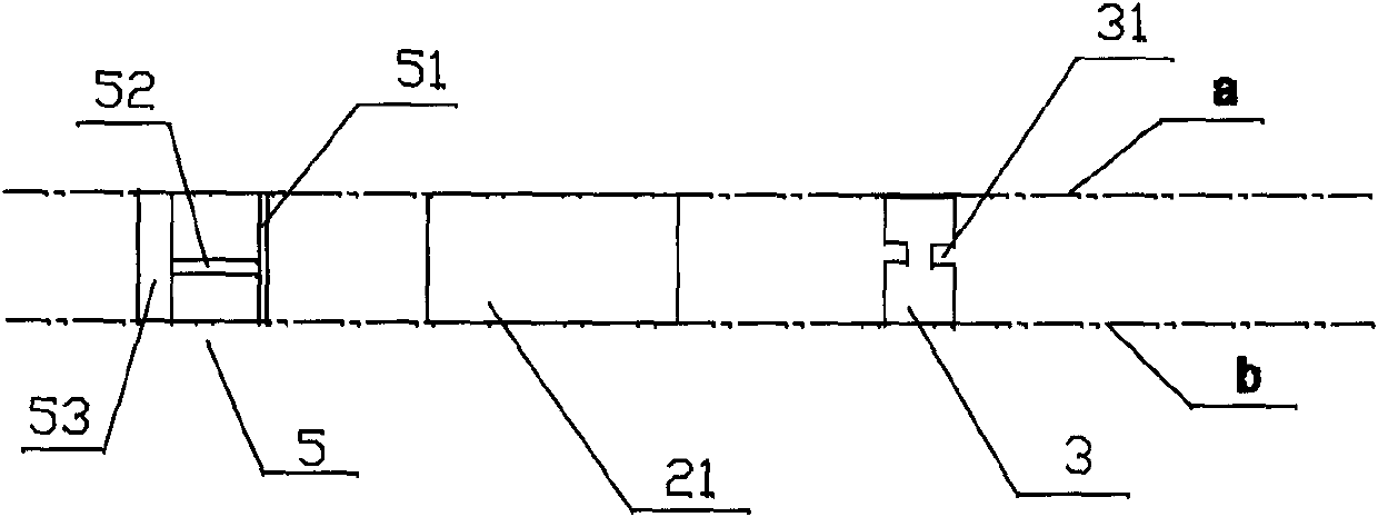
[0045] The planes where the edges of the tape of the tape roll 21 are located are plane a and plane b, and the distance between the plane a and plane b is not greater than the width of the tape.

[0046] The central axis 20 is perpendicular to the application direction of the adhesive tape of the tape roll 21, that is, perpendicular to the moving direction of the optical fiber laying device during construction, that is, when the tape roll 21 is installed on the gluing module 2, the tape roll 21 is in the The optical fiber laying device is placed vertically, t...

Embodiment 2

[0061] see Figure 5 , a kind of optical fiber laying device, is different from the optical fiber laying device described in embodiment 1:

[0062] The optical fiber laying device also includes a tightening module 32; the tightening module 32 is a double-arm slot structure, and the junction of the two arms is a slot for the passage of the optical fiber; the slot is arranged on the tightening module 32 a portion between said plane a and plane b;

[0063] The two arms of the tightening module 32 are elastic structures, and the elastic structures have opposite thrusts on the optical fibers passing through the slot, so that the optical fibers can be fastened in the slot without slipping; The area between the pressing module and the tightening module 32 is in a stretched state; for example, the elastic structure can be two opposite springs, both of which are in a compressed state.

[0064] This embodiment also provides an optical fiber laying method, which is different from the o...

Embodiment 3

[0068] see Figure 6 , a kind of optical fiber laying device, is different from the optical fiber laying device described in embodiment 1:

[0069] The limiting module 33 is a suspension beam arranged on the inner casing 1 of the optical fiber laying device, and the center of the suspension beam is provided with a through hole for the optical fiber to pass through; the through hole is provided when the suspension beam is on the plane a and plane b During construction, after the optical fiber passes through the through hole, it is always limited in the space between plane a and plane b, so that the optical fiber can always be covered by adhesive tape, avoiding the swing of the optical fiber during construction The amplitude is too large, thus achieving the purpose of adhesive tape to cover the optical fiber;

[0070] This embodiment also provides an optical fiber laying method, which is different from the optical fiber laying method described in Embodiment 1 in that:

[0071]...


PUM


Abstract

The invention relates to a device for laying fibers, which comprises a shell, an idler wheel, a gluing module, a limiting module and a compacting module, wherein the idler wheel, the gluing module, the limiting module and the compacting module are all arranged on the shell; the gluing module can rotate around a core shaft and is used for assembling an adhesive tape roll and placing fibers stuck and covered by the adhesive tape; the core shaft is vertical to the moving direction of the device for laying fibers in construction process; the limiting module has a limiting structure which is used for restraining the fibers and positioning the fibers at the position capable of being stuck and covered by the adhesive tape; the compacting module is used for applying force to the adhesive tape sticking and covering the fibers; and the idler wheel is arranged on the bottom of the device for laying fibers and is used for moving the device for laying fibers in a rolling manner. The invention also provides a method for laying fibers. The device and method provided by the invention have the advantages that the construction efficiency is high, the laid fibers are beautiful, the maneuverability is high, the device is portable, and the like.

Description

technical field [0001] The invention relates to an optical fiber laying device and method, in particular to an optical fiber laying device and method at a construction site. Background technique [0002] Optical fiber is a filament drawn from quartz. Because it is very fragile and easy to break, one or more optical fibers will be placed in a loose tube during production, and then filled with ointment; then a strengthening core (for Increase the strength of the optical cable) and the outer sheath (such as aluminum foil layer and polyethylene sheath) and so on become the optical cable. [0003] Since the optical fiber can sense the change of ambient temperature and / or strain, the optical fiber cable is used for temperature measurement or strain measurement in many occasions. [0004] When the distributed optical fiber temperature sensing system uses the sensing optical cable for temperature measurement, the sensing optical cable is not only the transmission medium, but also t...

Claims


Application Information

Patent Timeline
Patent Type & Authority Patents(China)
IPC IPC(8): G02B6/46G01K11/32
Inventor 孙亚楚张艳辉王东升郭锴
Owner FOCUSED PHOTONICS
Why Eureka
Try Eureka