
Method and device for producing paths of coherent light carriers

A production method and technology of a production device, applied in the field of optical communication, can solve the problems of difficult to find radio frequency amplifiers, fragile modulators, transmission performance limitations, etc., and achieve the effects of reducing the number of light sources, prolonging service life, and simplifying phase estimation

Active Publication Date: 2011-08-17
WUHAN POST & TELECOMM RES INST CO LTD
View PDF6 Cites 20 Cited by
  • Summary
  • Abstract
  • Description
  • Claims
  • Application Information

AI Technical Summary

Problems solved by technology

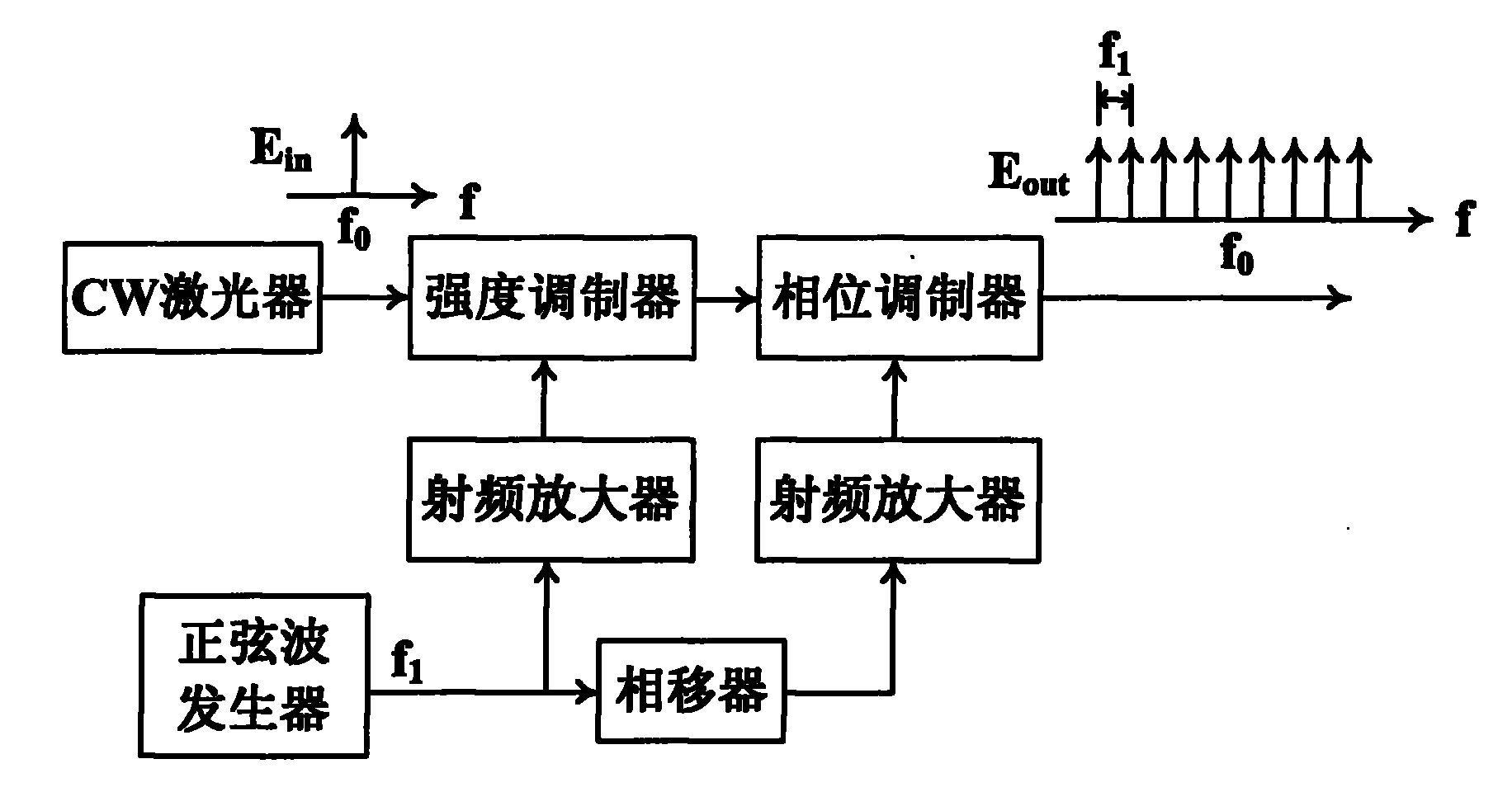
(OFCs mentioned below refer to OFCs based on strong E / O modulation, and will not be specifically pointed out.) The biggest disadvantage of the second OFC is that it requires a high RF voltage (over 24V) for driving. It can be considered that the higher the RF voltage, the greater the number of comb lines that meet certain power flatness requirements
On the one hand, this shortcoming makes it difficult to find a suitable low-cost commercial RF amplifier; on the other hand, excessive RF voltage can easily damage the modulator
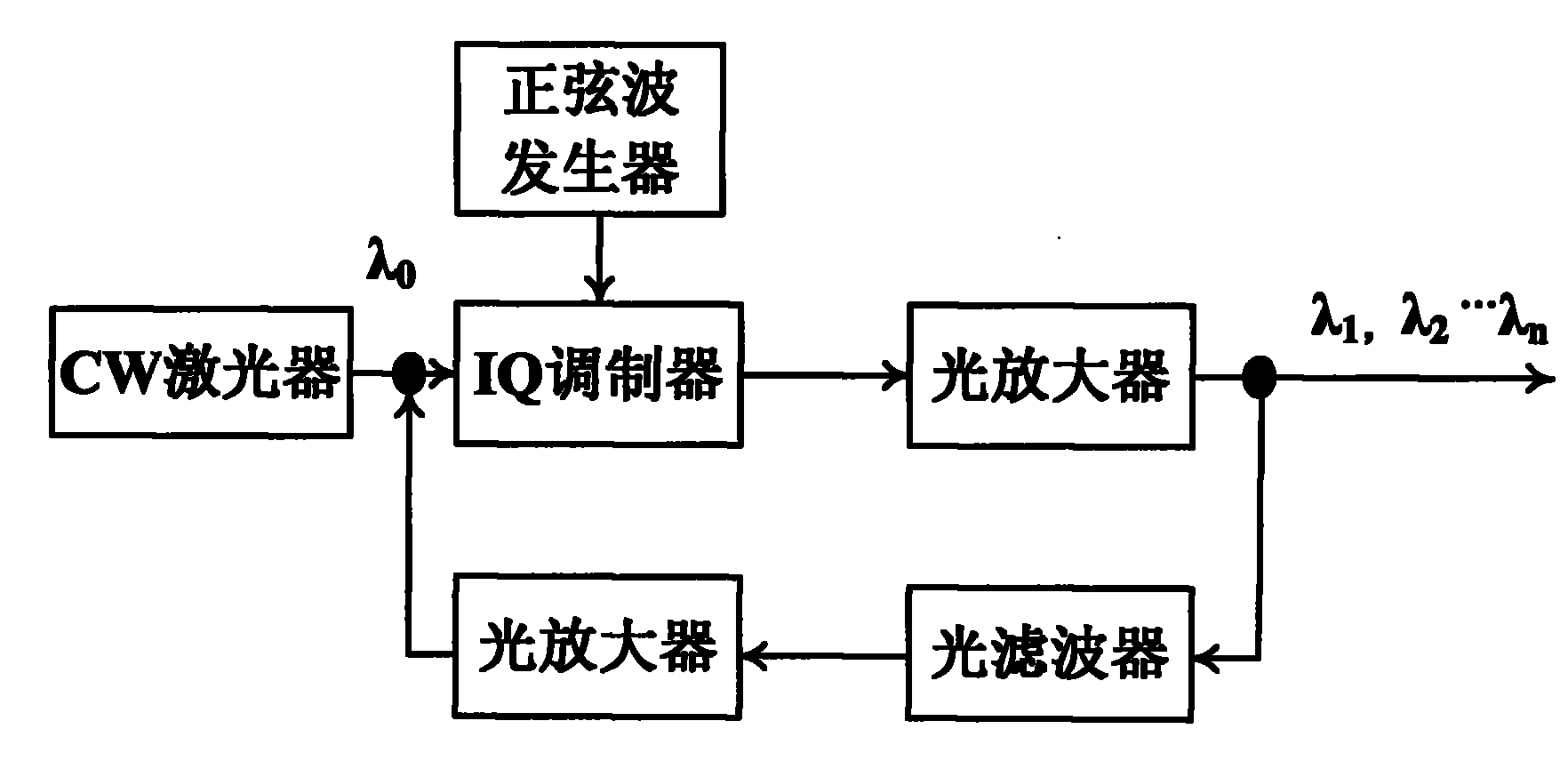
[0008] RFS technology does not require high voltage RF drivers, see figure 2 As shown, the flatness of the optical carrier generated by RFS is good, but the multiple cycle amplification of the optical amplifier in the loop introduces higher ASE (Amplified Spontaneous Emission, spontaneously emitted large radiation) noise, making the OSNR (Optical Signal Noise Ratio, optical signal-to-noise ratio) is not as good as OFC technology
Therefore, the transmission performance of the system using RFS technology is greatly limited

Method used


Image

  • Method and device for producing paths of coherent light carriers
  • Method and device for producing paths of coherent light carriers
  • Method and device for producing paths of coherent light carriers

Examples


Embodiment Construction

[0032] The present invention will be further described in detail below in conjunction with the accompanying drawings and embodiments.

[0033] The multi-channel coherent optical carrier generation method provided by the embodiment of the present invention includes the following steps:

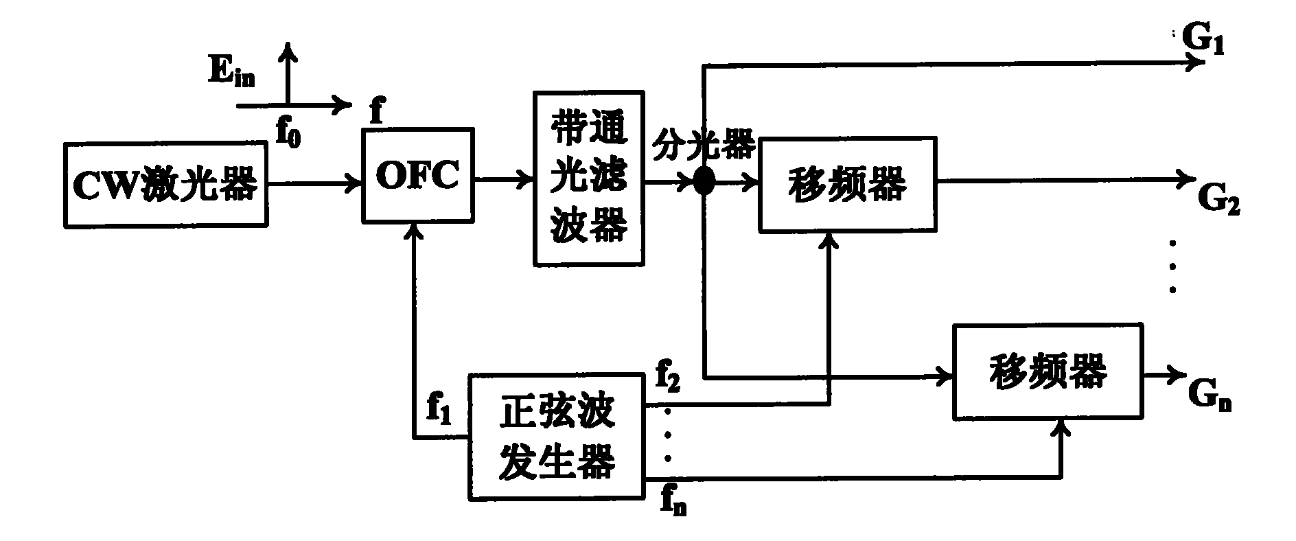
[0034] A. Send the specific wavelength laser with stable wavelength output by the continuous wave laser into the optical frequency comb to generate several frequency comb lines, and then pass through the bandpass optical filter to obtain N 1 root frequency comb line, N 1 is a positive integer greater than 1;

[0035] B. The N 1 The root frequency comb line is divided into n-channel signals, n is a positive integer greater than 1, and the second-to-n-channel signals are respectively frequency-shifted, and the first-channel signal and the second-to-n-channel signals after frequency shifting Signals together form the required multi-channel coherent optical carrier.

[0036] N in step B 1 The ...


PUM


Abstract

The invention discloses a method and a device for producing a plurality of paths of coherent light carriers, which relate to the field of optical communication. The method comprises the following steps of: transmitting laser light, output by a continuous wave laser, with a stable given wavelength into an optical frequency comb to produce a plurality of frequency comb lines, and obtaining N1 frequency comb lines by using a band path optical filter, wherein N1 is a positive integer more than 1; and dividing the N1 frequency comb lines into n paths of signals, performing frequency shifting on the second to nth paths of signals respectively, and commonly forming the required plurality of paths of coherent light carriers by using the first path of signals and the second to nth paths of frequency-shifted signals, wherein n is the positive integer more than 1. By the method and the device, the requirements of the optical frequency comb (OFC) on devices such as a radio frequency amplifier, a modulator and the like can be reduced, a required number of light carriers can be produced, relatively higher flatness and a higher optical signal to noise ratio (OSNR) are ensured, and the practicability of an orthogonal frequency division multiplexing (OFDM) system is further improved.

Description

technical field [0001] The invention relates to the field of optical communication, in particular to a method and device for generating multi-channel coherent optical carriers. Background technique [0002] With the continuous and strong growth of Internet traffic, the underlying optical transmission needs to continuously increase the transmission capacity to meet the huge bandwidth demand. Optical transmission capacity mainly depends on the number of channels available in the fiber and the transmission rate per channel. The ultra-dense wavelength division multiplexing system can effectively increase the number of channels. If each channel is equipped with an independent light source, it means that the number of light sources may reach hundreds. At present, the channel rate of the commercial system has reached 40Gbps, and the rate of the laboratory system has reached 400Gbps, or even 1Tbps. For systems with a channel rate exceeding 100Gbps, the industry basically forms a c...

Claims


Application Information

Patent Timeline
IPC IPC(8): H04B10/12H04L27/26H04B10/2575
Inventor 张新全杨铸贺志学杨奇
Owner WUHAN POST & TELECOMM RES INST CO LTD
Learn More