Amplified electrokinetic fluid pumping switching and desalting
A microfluidic device, voltage technology, applied in the field of changing the flow direction and direct seawater desalination, amplifying pumping, can solve the problems of consumption, membrane fouling, high cost, etc.
- Summary
- Abstract
- Description
- Claims
- Application Information
AI Technical Summary
Problems solved by technology
Method used
Image

Examples
example 2
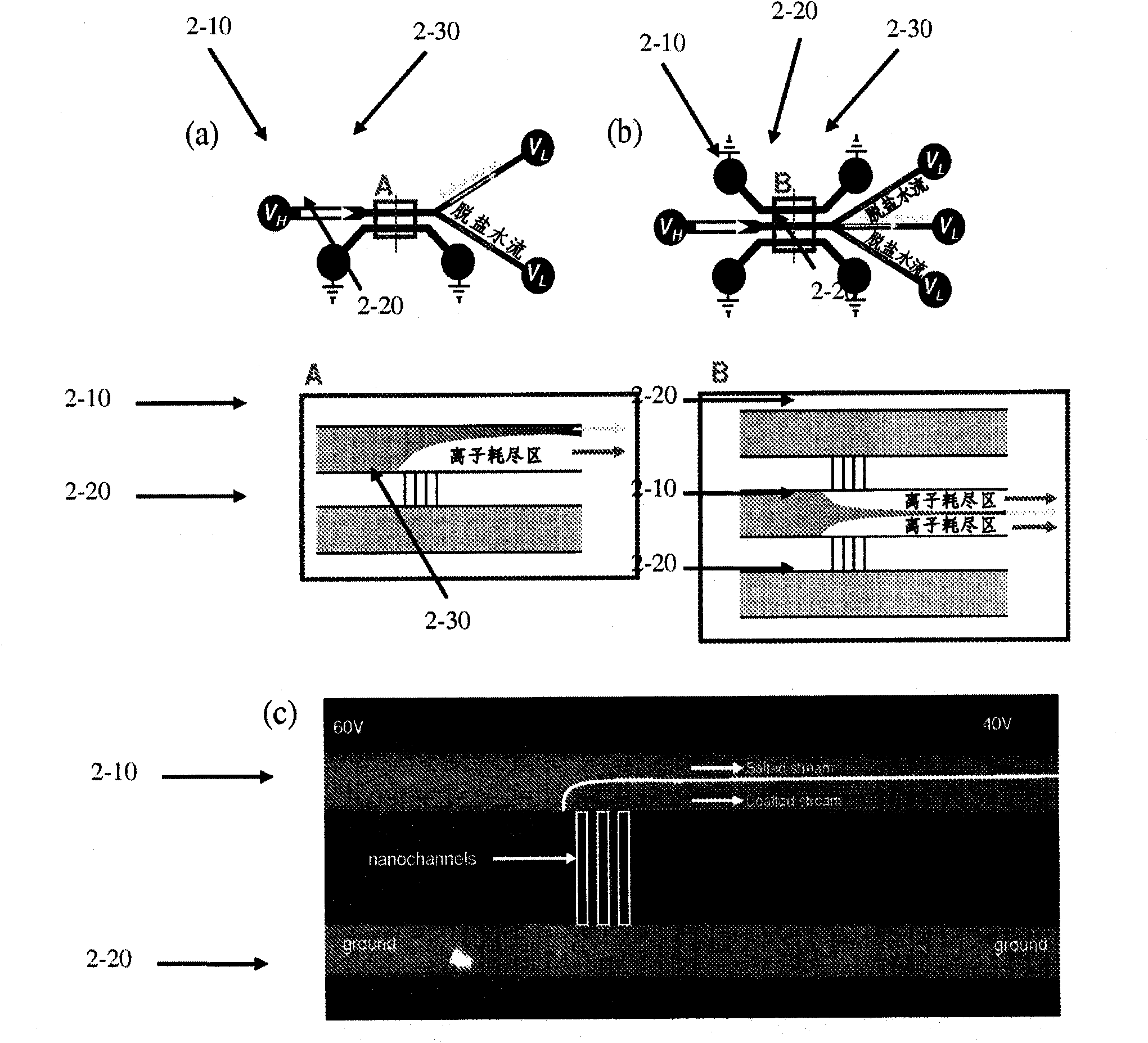
[0224] Such as Figure 11 As shown in (a), once ICP starts, a depletion zone forms within 1 s, diverting charged ions (represented by dye molecules) into the "saline" water stream. Such as Figure 11 As shown in (b), the ICP layer becomes virtual for all negatively charged particles and positively charged particles (including most solid particles, microorganisms and biomolecules (proteins, bacteria, viruses, red blood cells, white blood cells, etc.) found in seawater. barrier layer. Figure 11 The device shown in (b) has microchannel inlet dimensions of 100 μm wide by 15 μm deep in order to clearly demonstrate the movement of leukocytes. This is because most aquatic microorganisms and microparticles have a non-zero (usually slightly negative) zeta potential. Thus, small salt ions and large microorganisms can be removed from the output desalted fluid. Therefore, this process is very attractive for seawater desalination directly from nature. Because most of the ions are rem...
example 3
[0228] Each microchannel was connected to a nanoflow sensor (Upchurch, N-565) for in situ measurement of the actual flow rate out of each microchannel. Such as Figure 14 As shown, the inlet flow rate is almost equally divided into the branched microchannels. Example 3 power consumption
[0229] The steady-state current required by the unit device of the present invention is 1 μA (in a device with a microchannel cross section of 100 μm×15 μm, the output flow rate of seawater desalination is 0.25 μL / min) or ~30 μA (in a device with a microchannel cross section of 500 μm×100 μm, the seawater Desalting output flow rate is 10 μL / min). Therefore, the power consumption of each unit device is about 75 μW˜2250 μW. Therefore, the energy efficiency of the desalination mechanism is 5Wh / L (75μW / 0.25μL / min) to 3.75Wh / L (2250μW / 10μL / min). In addition to this, the energy required to transport the fluid through the microchannel is 0.041 mWh / L to 1.55 mWh / L. When the flow rate Q=0.25 μL / m...
example 4
[0231] Parallelization of an example 4-unit device
[0232] The critical desalting step takes place within a short distance within the microchannel, so it is estimated that the required lateral space (area) for a unitary microfluidic device is approximately 1 mm x 1 mm. A large number of unit devices are arranged in parallel on the scale of 6-8 inch wafers (17600-31400mm 2 , which allows scaling up to 1.5 x 10 4 ~3×10 4 ) enables a production of 150 mL / min to 300 mL / min in a small system, which is well suited for portable seawater desalination applications. Such as Figure 15 In this system, gravity is used to pass the fluid through a pre-filter stack to remove large particles / impurities, and through a large number of parallel arrays of ICP desalination devices (similar to a home filtration system) to eliminate pathogens and salts share.
[0233] For comparison, gravity-driven commercial household water purification systems (non-desalination systems) have ~200 mL / min throug...
PUM
 Abstract
Description
Claims
Application Information
 - R&D
- Intellectual Property
- Life Sciences
- Materials
- Tech Scout
- Unparalleled Data Quality
- Higher Quality Content
- 60% Fewer Hallucinations
Browse by: Latest US Patents, China's latest patents, Technical Efficacy Thesaurus, Application Domain, Technology Topic, Popular Technical Reports.
© 2025 PatSnap. All rights reserved.Legal|Privacy policy|Modern Slavery Act Transparency Statement|Sitemap|About US| Contact US: help@patsnap.com