

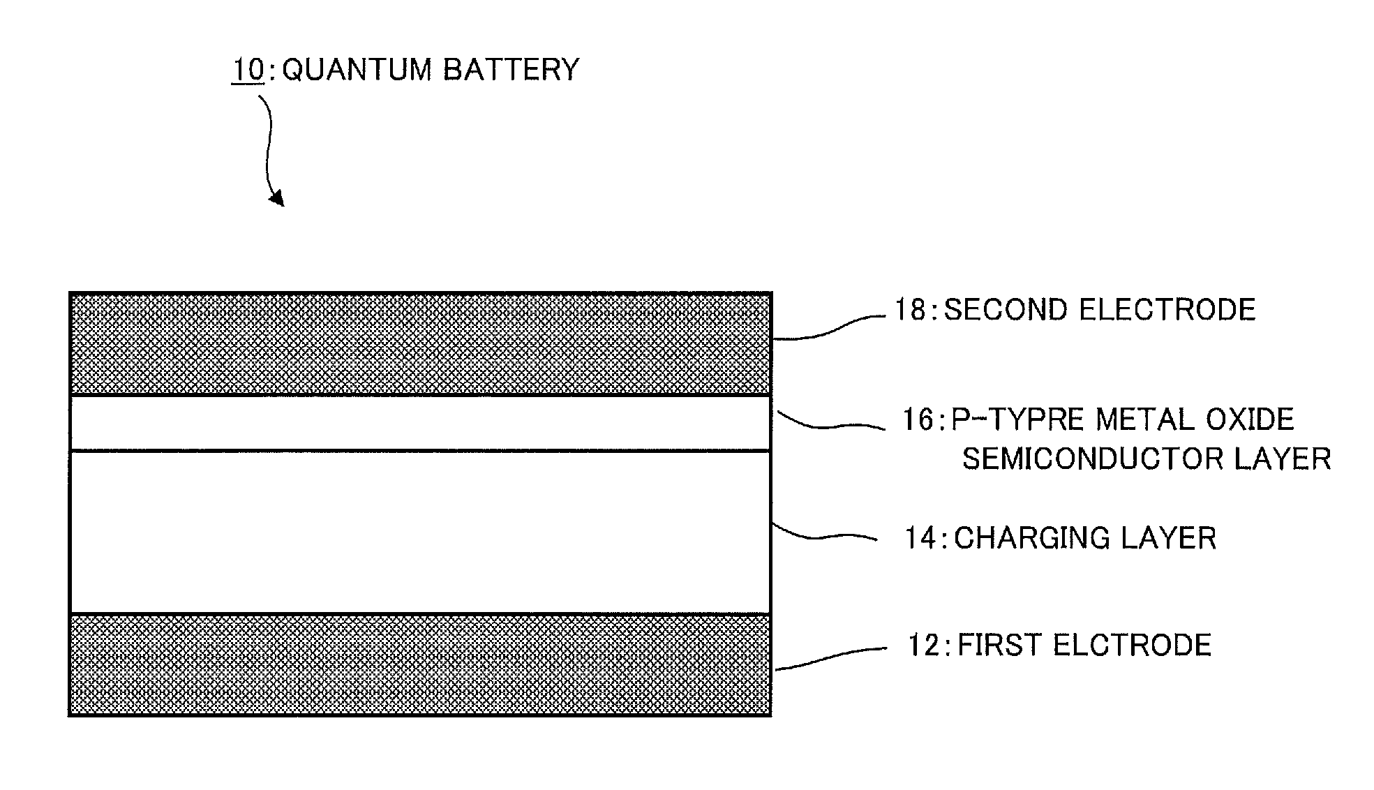
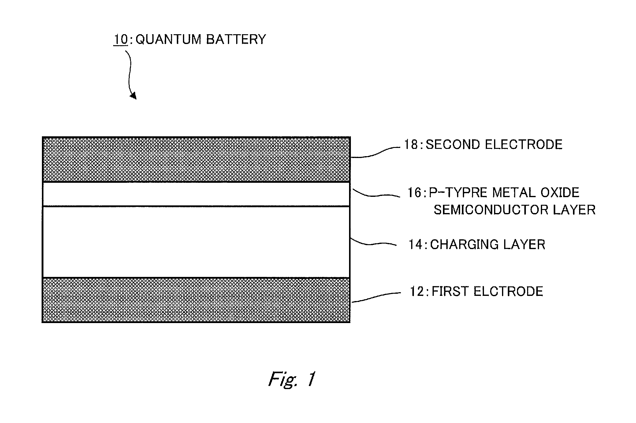
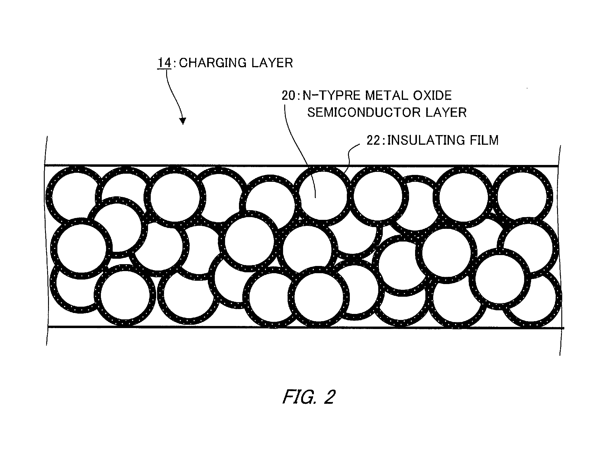
Repeatedly chargeable and dischargeable quantum battery
a quantum battery, rechargeable technology, applied in the direction of electrochemical generators, secondary cell details, transportation and packaging, etc., can solve the problems of affecting the service life and degrading characteristics of the battery, and achieve the effect of suppressing the oxidation of the electrode due to changes over time and preventing deterioration or peeling
- Summary
- Abstract
- Description
- Claims
- Application Information
AI Technical Summary
Benefits of technology
Problems solved by technology
Method used
Image

Examples
example 1
[0087]FIG. 16 illustrates an example of a quantum battery 100 prototyped on a glass substrate according to the invention using a polyimide film 94 as the substrate 64.
[0088]The polyimide film 94 is 4 μm-thick, and a 50 nm-thick chromium film 96 having passivation characteristics and a 300 nm-thick copper layer 30 are laminated on the polyimide film. Furthermore, a 50 nm-thick chromium layer 96 is laminated. When manufacturing the above-described charging layer 14, approximately 300° C. heat is generated in the manufacturing process.
[0089]At this phase, an ultraviolet ray 38 is irradiated on the charging layer 14 so as to cause a photo-excited structural change of titanium dioxide 32 and form a new energy level 44.
[0090]After that, a 150 nm-thick nickel oxide film 50 is formed, and a 50 nm-thick chromium film 96 and a 300 nm-thick copper film 48 are laminated, thereby completing a quantum battery 100.
[0091]When manufacturing the quantum battery 100, it is possible to use a gas-phase ...
example 2
[0092]FIG. 17 is an example of a quantum battery 102 prototyped using an alloy as a metallic material.
[0093]The polyimide film 94 is 4 μm-thick, and a 50 nm-thick chromium film 96 having passivation characteristics and, similarly, a 300 nm-thick aluminum copper alloy film 104 having passivation characteristics are laminated on the polyimide film. Furthermore, a 50 nm-thick chromium film 96 is laminated, and a 50 nm-thick titanium dioxide film 32 is laminated on the chromium film as the n-type metal oxide semiconductor layer. Next, a 1000 nm or more-thick film of titanium dioxide 32 miniaturized and coated with silicone 34 is laminated so as to produce a charging layer 14. In this case as well, similarly to Example 1, approximately 300° C. heat is generated in the manufacturing process when manufacturing the above-described charging layer 14.
[0094]Furthermore, similarly to Example 1, an ultraviolet ray is irradiated on the charging layer 14 so as to cause a photo-excited structural c...
PUM
 Abstract
Description
Claims
Application Information