Vertical-horizontal combined machining centre

A compound machining center, vertical and horizontal technology, applied in the direction of metal processing equipment, metal processing machinery parts, manufacturing tools, etc., can solve the problem that the structure of the machine tool cannot meet the requirements of high-efficiency precision machining, cannot perform left and right feed movement, and cannot perform up-and-down precision feed give exercise and other questions

Active Publication Date: 2011-08-24
HANGZHOU DATIAN CNC MACHINE TOOL
View PDF6 Cites 33 Cited by
  • Summary
  • Abstract
  • Description
  • Claims
  • Application Information

AI Technical Summary

Problems solved by technology

[0003] The need of the present invention is to provide a vertical-horizontal compound machining center, which mainly solves the existing problems in the prior art that the grinding head and the planer tool holder are set on the column, and the left and right feed movements cannot be performed; and the milling and boring head set on the beam, Turning tool holders, grinding heads, and planer tool holders cannot perform precise up-and-down feed movements, and the machine tool structure cannot meet the requirements of high-efficiency and precision machining.

Method used


Image

  • Vertical-horizontal combined machining centre
  • Vertical-horizontal combined machining centre

Examples


Embodiment

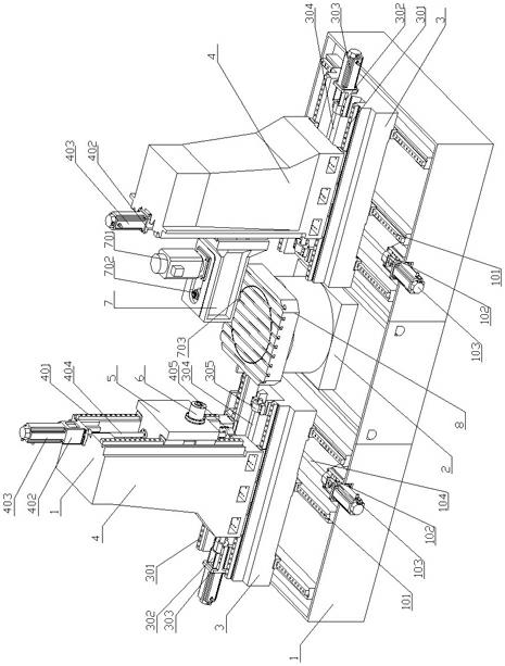
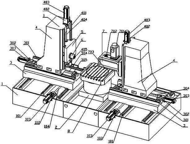
[0015] Embodiment: the vertical and horizontal compound machining center of this example, such as figure 1 , there is a base 1, a fixed workbench 2 is arranged in the middle of the base, and a numerical control rotary workbench 8 is installed on the fixed workbench 2. Three base slide rails 101 are fixed on the bases at both ends of the fixed workbench, and a sliding seat 3 that can move forward and backward is slidably connected to the base slide rails at both ends. Base motor 103 is fixed with base motor seat 102 on the base, base motor is connected with base screw mandrel 104, base screw mandrel connects slide seat 3, and the other end of base screw mandrel is connected with base screw mandrel bearing seat, base screw mandrel nut seat, Bearings are arranged in the base screw bearing seat. Two sliding seats 3 are fixed with two sliding seat slide rails 301, and the sliding seat slide rails are slidably connected with uprights 4 that can slide left and right. Seat motor 303...


PUM


Abstract

The invention relates to a numerically controlled machine tool, in particular to a vertical-horizontal combined machining centre, which is mainly used for solving the technical problems of the prior art that: a grinding head and a planer tool frame are arranged on a stand column of the machine tool, the machine tool cannot perform a feed movement transversely; a milling boring head, a tool holder, a grinding head and a planer tool rest arranged on a beam cannot carry out a precise feed movement up and down; and the machine tool structure cannot meet the requirement of efficient and precise processing. The machining centre comprises a base, wherein a fixed workbench is arranged in the centre of the base; the two ends of the base are movably connected with two sliding seats capable of moving horizontally through a base sliding device; the two sliding seats are movably connected with stand columns through sliding devices of the sliding seats, wherein one stand column is movably connectedwith a horizontal sliding saddle which is fixed with a horizontal spindle, while the other stand column is movably connected with a vertical sliding saddle which is fixed with a vertical spindle device; and the base sliding device, the sliding devices of the sliding seats and the stand column sliding devices are connected with a numerically controlled electric device.

Description

technical field [0001] The invention relates to a numerically controlled machine tool, in particular to a vertical and horizontal composite machining center. Background technique [0002] The CNC gantry machine tool is mainly composed of a bed, a worktable, left and right columns, a beam, a saddle, a main gearbox, a console, an electrical control box, and a drive control device. It can complete milling, drilling, reaming, boring and other multi-process processing, and is suitable for rough and fine processing of large and medium-sized parts in various industries. The Chinese patent discloses a CNC gantry car milling, boring, planing and grinding heavy-duty machine tool (publication number: CN 101502933A), which consists of a bed, a reciprocating table, a composite column, a beam, a top beam, a rotary power head, a chuck, a tailstock, The main transmission mechanism, grinding head, milling and boring head, planer tool holder, turning tool holder, electrical control system, e...

Claims


Application Information

Patent Timeline
IPC IPC(8): B23P23/00B23Q5/40
Inventor 王元庆
Owner HANGZHOU DATIAN CNC MACHINE TOOL
Why Eureka
Try Eureka