Method for detecting residual stress based on inverse problem

A technology of residual stress and detection method, applied in the direction of measuring force, measuring device, special data processing application, etc., can solve the problem of not taking into account the different calibration coefficients of residual stress, not considering the influence of removing residual stress, and insufficient residual stress data. Accuracy and other issues, to achieve the effect of easy operation and promotion, low cost and strong practicability

Active Publication Date: 2011-08-24
罗键
View PDF5 Cites 22 Cited by
  • Summary
  • Abstract
  • Description
  • Claims
  • Application Information

AI Technical Summary

Problems solved by technology

The current detection method does not take into account the influence of removing material at a certain depth on the measured component on the residual stress of the detected workpiece, nor does it take into account the influence of different calibration coefficients of residual stress at different depths
And for a multi-layer drilling, or for the measured workpiece with non-planar spherical or cylindrical structure or a newly discovered material, it is difficult to use the small hole method to realize the residual stress due to the lack of corresponding residual stress calibration coefficients. Measurement, or the data of the measured residual stress is not very accurate

Method used


Image

  • Method for detecting residual stress based on inverse problem
  • Method for detecting residual stress based on inverse problem
  • Method for detecting residual stress based on inverse problem

Examples


specific Embodiment 1

[0043] The plane structure workpiece is drilled once to detect the residual stress. It is a stainless steel laser welded honeycomb panel with a length of 18cm, a width of 12cm, and a thickness of 2.0mm. The welding residual stress value is measured. The residual stress value of the workpiece is detected by the method of reverse thinking to detect the residual stress. Use ANSYS or ABAQUS numerical simulation software to calculate the residual stress calibration coefficient A=-5.87591418476E-07, B=-1.41076852438E-06 for the material and structure. Then the actual small hole stress release method is used to measure the strain value at this position. According to the residual stress calibration coefficient and the measured strain value, the detected welding residual stress is σ 1 = -516.98MPa and σ 2 = -483.15MPa.

specific Embodiment 2

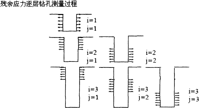
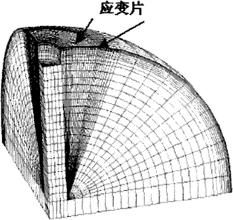
[0044] Detection of residual stress and its distribution along the thickness of non-planar structure workpieces. The test is a Q235 steel cylindrical structure. The diameter of the small hole is 2mm, and the holes are drilled layer by layer in 12 steps along the thickness direction. The number of drilling layers is 12, and the depth is 0.02mm, 0.04mm, 0.08mm, 0.12mm, 0.16mm, 0.2mm, 0.3mm, 0.4mm. , 0.5mm, 0.6mm, 0.8mm, 1.0mm. The residual stress calibration coefficient A obtained by self-programming calculation using this method jj The relationship between the sequence and the diameter of the sample cylinder is as follows Figure 5 Shown. There is a difference between the residual stress detected by the planar element using this method and the residual stress detected by the cylindrical element. The residual stress value of the cylindrical structure detected by the cylindrical element using this method is more accurate, and the detection error is less than 5%. The relationship...


PUM


Abstract

The invention discloses a method for detecting a residual stress based on an inverse problem. The method comprises the following steps of: calculating a residual stress calibration coefficient by adopting the contrary opinion based on the inverse problem and using a modern value simulation method, measuring a strain value of the residual stress calibration coefficient by an orifice method, and finally obtaining an actual residual stress value of a material or a structure through the obtained residual stress calibration coefficient and a residual stress detection and calculation model.

Description

Technical field: [0001] The invention belongs to the field of residual stress detection and relates to a computer-aided residual stress detection method based on inverse problems. Background technique: [0002] Various mechanical processes such as casting, cutting, welding, heat treatment, assembly, etc. will cause different levels of residual stress in the workpiece. The existence of residual stress, on the one hand, will reduce the strength of the workpiece and cause process defects such as deformation and cracking of the workpiece during manufacturing; on the other hand, it will change the size of the workpiece or make the fatigue strength and fatigue strength of the workpiece during the natural release process after manufacturing. Mechanical properties such as stress corrosion are reduced. Therefore, the measurement of residual stress is very important to ensure the safety and reliability of the workpiece. At present, the traditional measurement methods of residual stress a...

Claims


Application Information

Patent Timeline
Patent Type & Authority Applications(China)
IPC IPC(8): G01L1/00G01N19/00G06F17/50
Inventor 罗键王颖
Owner 罗键
Why Eureka
Try Eureka