Torsion fiber optic acceleration transducer

An acceleration sensor and sensor technology, which is applied in the direction of using optical devices to transmit sensing components and using inertial force for acceleration measurement, etc., can solve the problems of temperature compensation restricting the development of optical fiber sensors, low measurement frequency, and inability to cover the frequency range of traditional acceleration sensors. , to achieve the effect of stable and reliable layout, wide linear range, and improved linearity and stability

Active Publication Date: 2012-09-26
BEIJING CHANGCHENG INST OF METROLOGY & MEASUREMENT AVIATION IND CORP OF CHINA
View PDF0 Cites 1 Cited by
  • Summary
  • Abstract
  • Description
  • Claims
  • Application Information

AI Technical Summary

Problems solved by technology

In the existing design schemes of optical fiber acceleration sensors, most of them are based on the bending beam structure, and there are also tension and lever mechanisms as powerful supplements. However, the measurement frequency of existing products is low and cannot cover the frequency range of traditional acceleration sensors. In addition, due to the characteristics of fiber gratings, the problem of temperature compensation has also limited the development of fiber optic sensors to a certain extent.

Method used


Image

  • Torsion fiber optic acceleration transducer
  • Torsion fiber optic acceleration transducer
  • Torsion fiber optic acceleration transducer

Examples


Embodiment Construction

[0018] Embodiments of the present invention will be described in detail below in conjunction with the accompanying drawings.

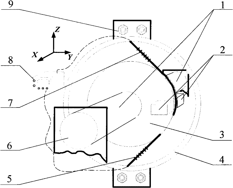
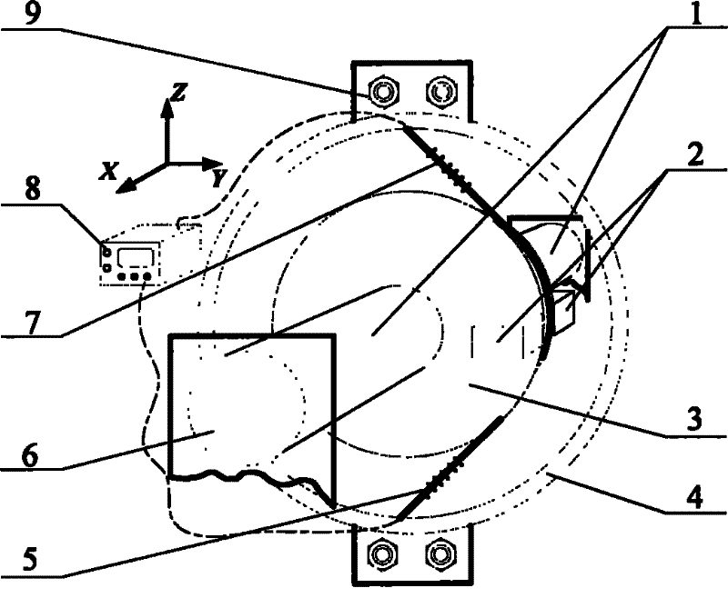
[0019] See attached figure 1 As shown, this kind of torsional differential temperature-compensated optical fiber acceleration sensor, at the midpoint of the elastic torsion shaft 1 fixed at both ends and the shell, uses the coaxial rotating disk 3 to connect and fix the mass block 2, and the mass block 2 is installed on the rotating On the disk 3, and the optical fiber with prestress is wound on the rotating disk 3, the fiber gratings 5 ​​and 7 of the two suspended sections have the same length and prestress, and their other ends are fixed on the same axis as the torsion shaft 1 and the rotating disk 3. The optical fiber of the shaft is installed on the ring 4, and the signal is continuously connected to the demodulation instrument 8 through the optical fiber, and the optical fiber installation ring 4 is connected with the sensor housing by installing ...


PUM


Abstract

The invention belongs to metering and testing technologies, and relates to a torsion fiber optic acceleration transducer. The transducer comprises an elastomer, a mass block, and a fiber bragg grating; two end parts of an elastic torsion shaft of the transducer are fixed on a shell of the transducer; the middle part of the elastic torsion shaft is provided with a rotary disc; the rotary disc is provided with an eccentric mass block; the fiber bragg grating with a prestressing force is wound on the periphery of the rotary disc; a leading-out terminal of the fiber bragg grating is fixed on an installation ring; the installation ring is fixed on the shell of the transducer; and an optical signal accesses a demodulation instrument via the leading-out terminal. The torsion fiber optic acceleration transducer has great difference from various design schemes of the conventional fiber optical acceleration transducers; factors of influencing sensitivity and a natural frequency are designed separately, so the sensitivity can be improved by winding a radius under the condition of not changing relevant parameters of the torsion shaft and the mass block, and the contradiction between the sensitivity and the natural frequency is solved; furthermore, by two sections of gratings with equal length and equal prestressing force, which are wound reversely, the temperature compensation problem of the sensor is solved.

Description

technical field [0001] The invention belongs to the measuring and testing technology, and relates to a torsional optical fiber acceleration sensor. Background technique [0002] Optical fiber sensing technology is a new technology developed in the mid-1970s. It is gradually formed along with the development of optical fiber and optical communication technology. It uses optical fiber as the transmission medium. When the environmental parameters of the fiber Bragg grating change, the transmission characteristics of the light wave will change accordingly. By using this characteristic of the fiber Bragg grating, it can realize the control of stress, vibration (including speed, acceleration, etc.), pressure, temperature, etc. , Humidity and other parameters measurement. Due to the advantages of anti-electromagnetic interference, high temperature and high pressure resistance, corrosion resistance, small size, light weight, and easy integration, fiber optic sensors are increasing...

Claims


Application Information

Patent Timeline
Patent Type & Authority Patents(China)
IPC IPC(8): G01P15/03G01D5/32
Inventor 王宇张毅翔薛景锋陈爽
Owner BEIJING CHANGCHENG INST OF METROLOGY & MEASUREMENT AVIATION IND CORP OF CHINA
Why Eureka
Try Eureka