Spot coupling and conversion device

A conversion device and light spot technology, which is applied in the coupling of optical waveguide, cladding fiber, optical waveguide light guide, etc., can solve the problem of low tolerance between light beam and single-mode fiber ferrule 3, poor tracking error index effect, and optical power output from the fiber. Drop and other problems, to achieve the effect of small docking loss, improve yield rate, and save energy

Inactive Publication Date: 2011-08-24
WUHAN TELECOMM DEVICES
View PDF3 Cites 5 Cited by
  • Summary
  • Abstract
  • Description
  • Claims
  • Application Information

AI Technical Summary

Problems solved by technology

[0002] At present, the coupling method adopted by the optical transmitting sub-module and the optical bi-directional sub-module is in series, such as figure 1 As shown, the spot replacement device 10 includes a semiconductor laser 1, a lens 2, a single-mode fiber ferrule 3 and a single-mode fiber 4 coupled in series, the disadvantage of this structure is that the light-through hole 31 of the single-mode fiber ferrule 3 The diameter is very small, resulting in a very low tolerance between the beam and the single-mode fiber ferrule 3. When there is a slight mismatch between the high-low temperature beam and the single-mode fiber ferrule, the optical power of the fiber will drop significantly, which is reflected in the industrial Tracking error metrics work poorly at temperature

Method used


Image

  • Spot coupling and conversion device
  • Spot coupling and conversion device
  • Spot coupling and conversion device

Examples


Embodiment Construction

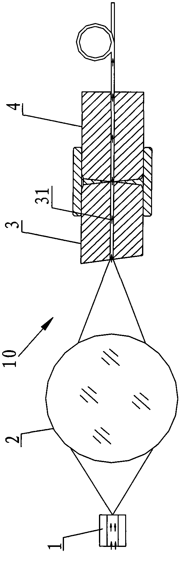
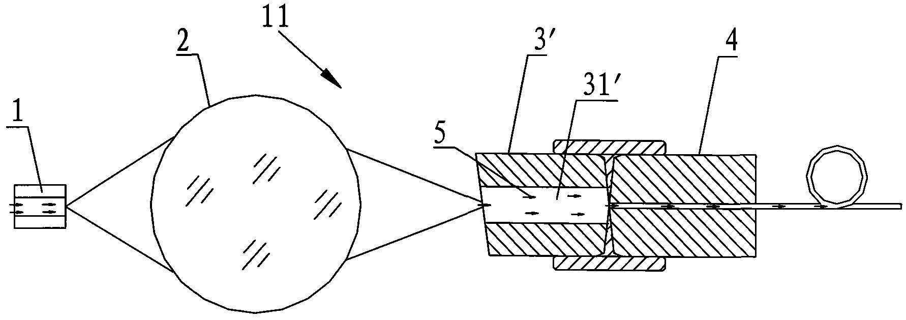
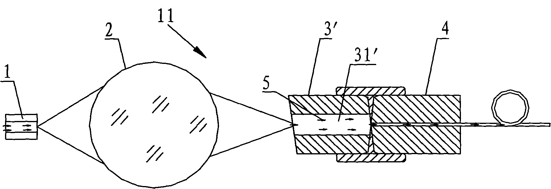
[0010] Such as figure 2 As shown, it is a schematic diagram of the application of the spot coupling conversion device of the present invention, and the spot coupling conversion device 11 plays the role of spot mode conversion in the series coupling link of the entire optical path. The spot coupling conversion device 11 includes a semiconductor laser 1, a lens 2, a multimode fiber ferrule 3', and a single-mode fiber 4 sequentially coupled in series. The optical fiber ferrule 3 has a larger optical hole 31', which increases the tolerance of the mismatch between the light beam 5 and the single-mode optical fiber 4, and at the same time limits the length of the multimode optical fiber ferrule 31' to ensure that the multimode The connection loss between the fiber ferrule 31 ′ and the single-mode fiber 4 is the smallest.

[0011] The above descriptions are only preferred embodiments of the present invention, and are not intended to limit the protection scope of the present inventi...


PUM


Abstract

The invention discloses a spot coupling and conversion device. The spot coupling and conversion device comprises a semiconductor laser, a lens, a fiber core insert, and a single-mode fiber, which are sequentially connected and coupled in series, wherein the fiber core insert is a multi-mode fiber core insert. The multi-mode fiber core insert used as the substitute of the existing single-mode fiber core insert has a larger optical aperture, which can improve the tolerance degree when the beam and the optical fiber are mismatched so as to ensure constant output power when the coupling of the beam and the fiber core insert has little mismatch. Meanwhile, the length of the multi-mode fiber core insert is limited to ensure the minimum coupling loss between the multi-mode fiber core insert and the single-mode fiber. The spot coupling and conversion device can improve the yield, save the energy and lower the cost.

Description

technical field [0001] The invention relates to a device for realizing light spot coupling conversion. Background technique [0002] At present, the coupling method adopted by the optical transmitting sub-module and the optical bi-directional sub-module is in series, such as figure 1 As shown, the spot replacement device 10 includes a semiconductor laser 1, a lens 2, a single-mode fiber ferrule 3 and a single-mode fiber 4 coupled in series, the disadvantage of this structure is that the light-through hole 31 of the single-mode fiber ferrule 3 The diameter is very small, resulting in a very low tolerance between the beam and the single-mode fiber ferrule 3. When there is a slight mismatch between the high-low temperature beam and the single-mode fiber ferrule, the optical power of the fiber will drop significantly, which is reflected in the industrial The tracking error metric works poorly at temperature. Contents of the invention [0003] In view of this, the technical p...

Claims


Application Information

Patent Timeline
Patent Type & Authority Applications(China)
IPC IPC(8): G02B6/42G02B6/02
Inventor 刘成刚米全林
Owner WUHAN TELECOMM DEVICES
Why Eureka
Try Eureka