Beam shaping device

A beam shaping and device technology, applied in optical components, optics, instruments, etc., can solve the problems of extremely high requirements for use methods and skills, high requirements for the stability of incident light sources, and insufficient uniformity. It has low requirements on using skills, is conducive to mass production, and has a wide range of applications.

Inactive Publication Date: 2011-08-24
INST OF OPTICS & ELECTRONICS - CHINESE ACAD OF SCI
View PDF4 Cites 9 Cited by
  • Summary
  • Abstract
  • Description
  • Claims
  • Application Information

AI Technical Summary

Problems solved by technology

At present, there are many methods for beam shaping, including macro lens, micro lens, liquid crystal light valve space and traditional phase subunit shaping technology, etc. These shaping technologies also have some problems, such as high adjustment accuracy of lens group and single output light field mode , the uniformity is not high enough; especially the traditional phase element is a single etching plate, and the element has high requirements on the incident beam. When it

Method used


Image

  • Beam shaping device
  • Beam shaping device
  • Beam shaping device

Examples


Example Embodiment

[0021] Embodiment one:

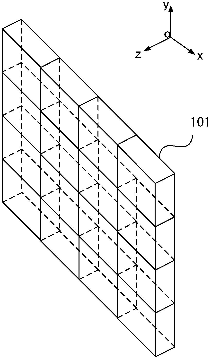
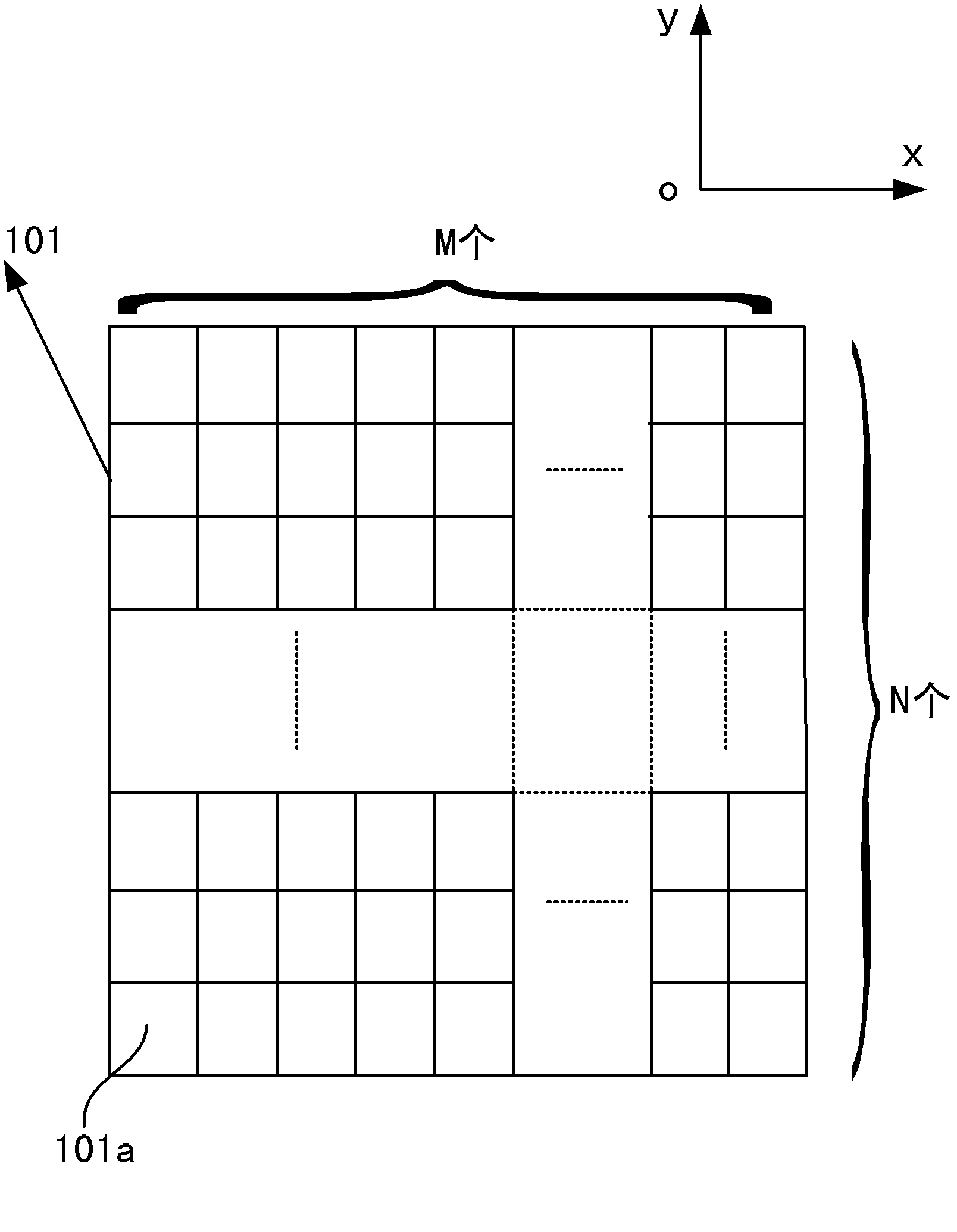
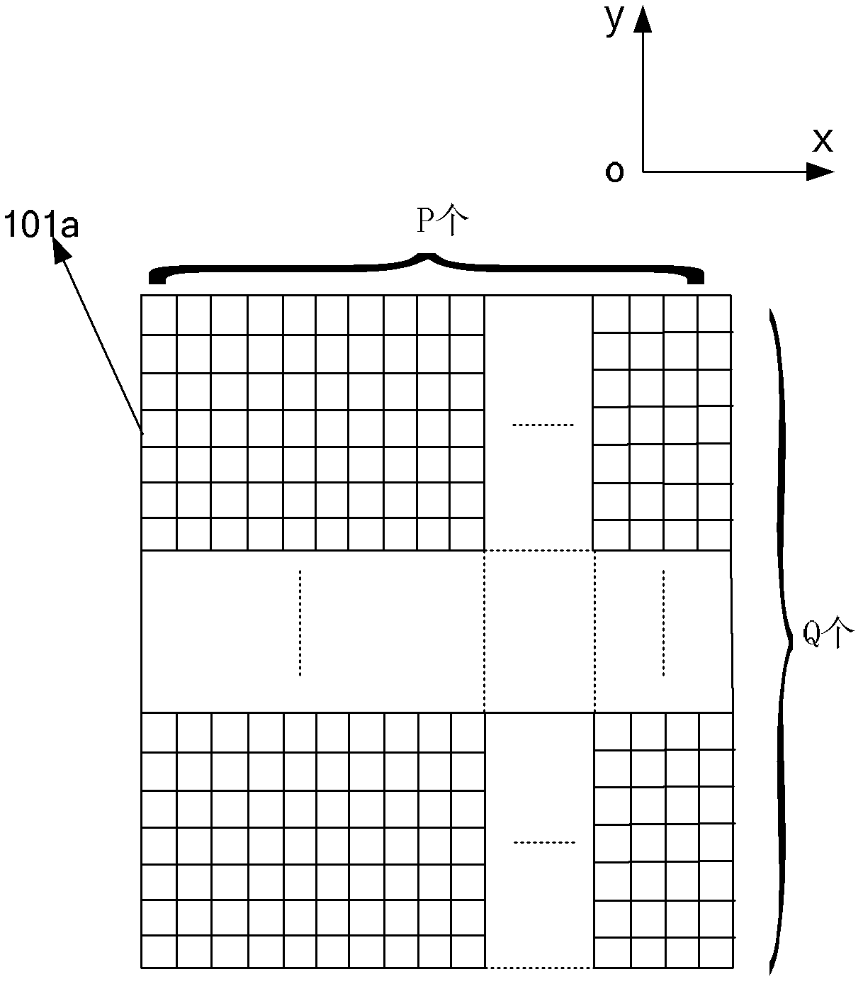
[0022] Figure 1a It is a schematic structural diagram of an array beam shaping device according to Embodiment 1 of the present invention, Figure 1b is a schematic cross-sectional view of the xoy plane structure of the beam shaping device according to Embodiment 1 of the present invention, Figure 2a It is a structural schematic diagram of the shaping unit of the present invention. One side surface of the working surface of the base 101 of the shaping device includes a plurality of shaping units 101a, the cross-section in the xoy plane of the shaping unit 101a is a rectangular structure, and the shaping units 101a are arrayed along the x-axis and the y-axis of the base 101 of the shaping device distribution, such as Figure 1b As shown, M columns of shaping units 101a (integer of M ≥ 1) are distributed along the x-axis of the base 101 of the shaping device, and N rows of shaping units 101a (integer of N ≥ 1) are distributed along the y-axis of the b...

Example Embodiment

[0029] Embodiment two:

[0030] Figure 5 It is a schematic cross-sectional view of the xoy plane of the beam shaping device according to Embodiment 2 of the present invention. The base 101 of the beam shaping device is circular, and the shaping units 101a inside it are rectangular and irregular in shape. Each shaping unit 101a is distributed in an array along the x-axis and the y-axis. There are tiny gaps between adjacent shaping units 101a. gap. The size of the shaping unit 101a is on the order of millimeters. M shaping units 101a (an integer of M≥1) are distributed along the x-axis, and N shaping units 101a (an integer of N≥1) are distributed along the y-axis, that is, the number of shaping units 101a in the x-axis and the y-axis The number can be 2 or 3 or more than 3, but it must be ensured that M and N are not 1 at the same time. When M=N=1, it is a common optical shaping unit. The image structure of the phase sub-unit in the shaping unit 101a is the same as the calc...


PUM


Abstract

The invention relates to a beam shaping device. The beam shaping device comprises beam shaping units which are distributed in an array mode, wherein each beam shaping unit comprises a plurality of phase sub units; and each beam shaping unit can independently realize beam shaping. The beam shaping device is used for acquiring device phase distribution data by a phase inversion algorithm according to the requirements of beam far fields on light intensity distribution, and an acquired phase distribution form is formed on the device by an etching method or an impressing method, so that the beam shaping device which can realize any shapes or meets the different requirements on the light intensity distribution, particularly, the beam shaping device capable of acquiring uniform light intensity distribution can be constructed. The beam shaping device can be used for transformation and shaping of light source outgoing beams of hot light sources, solid lasers, excimer lasers, semiconductor lasers and the like.

Description

technical field [0001] The invention relates to a beam shaping device, in particular to a beam shaping device with an array phase structure. Background technique [0002] Generally, when using a laser, it is expected that the intensity of the emitted beam has a Gaussian distribution, and the Gaussian distribution of most beams is not always ideal. Only solid-state lasers are easier to obtain Gaussian beams, such as the beams of excimer lasers are usually very unsatisfactory. Obvious intensity fluctuations can be observed, the beam is always asymmetrical, and the shape of the spot is irregular, and the intensity distribution of different pulsed beams may be different, and there are no rules to follow. In most application fields, the intensity distribution of the light field is required to be stable, and the spot size, shape and intensity distribution can be controlled freely, especially to achieve regular and stable spot shape and uniform distribution of light intensity. At ...

Claims


Application Information

Patent Timeline
IPC IPC(8): G02B27/09
Inventor 林妩媚廖志杰邱传凯刘银辉邢廷文张海波
Owner INST OF OPTICS & ELECTRONICS - CHINESE ACAD OF SCI
Why Eureka
Try Eureka