Micromechanical component and method for the production thereof

A technology of micromechanical components and structures, applied in the field of manufacturing such components, can solve the problems of escaping gas, changing pressure, etc.

Active Publication Date: 2011-08-24
ROBERT BOSCH GMBH
View PDF5 Cites 9 Cited by
  • Summary
  • Abstract
  • Description
  • Claims
  • Application Information

AI Technical Summary

Problems solved by technology

But the problem is that the remainder of the solvent may remain in the sealing glass, and thus in the cavity gas escapes and changes the predetermined pressure

Method used


Image

  • Micromechanical component and method for the production thereof
  • Micromechanical component and method for the production thereof
  • Micromechanical component and method for the production thereof

Examples


Embodiment Construction

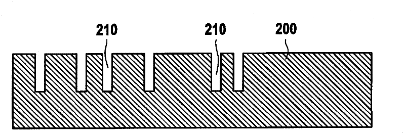
[0016] the following Figures 1 to 7 The production of a micromechanical component 300 is shown schematically, which can be used, for example, as an inertial sensor in a motor vehicle. During manufacture, processes and materials conventional in semiconductor technology can be used.

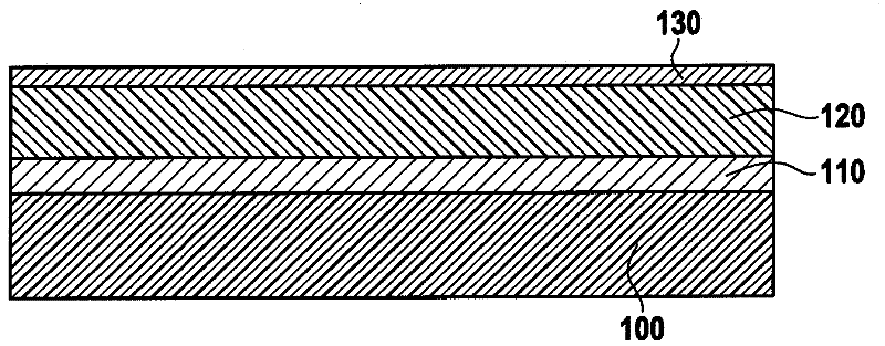
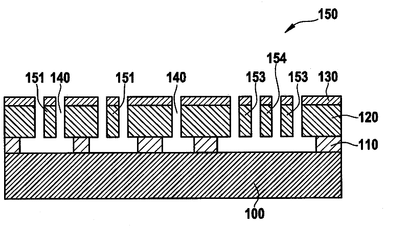
[0017] figure 1 and 2 The production of a functional substrate 100 with a micromechanical structure or MEMS structure 150 is shown for a component 300 , initially a substrate 100 is provided, which comprises, for example, a semiconductor material such as silicon. Substrate 100 may be a commonly used wafer having a diameter of, for example, 8 inches (200 mm).

[0018] Next on the substrate 100 as in figure 1 A sacrificial layer (Opferschicht) 110 is applied as shown in and a functional layer 120 is applied on this sacrificial layer 110 . The sacrificial layer 110 preferably comprises silicon oxide. The functional layer 120 may be a so-called epitaxial polysilicon layer, ie a polysilicon laye...


PUM


Abstract

The invention relates to a method for producing a micromechanical component (300) that comprises providing a first substrate (100), forming a microstructure (150) on the first substrate (100), wherein the microstructure (150) comprises a moving function element (151), providing a second substrate (200), and forming in the second substrate (200) an electrode (251) for capacitively measuring a deflection of the function element (151). The method further comprises connecting the first and the second substrates (100; 200), wherein a closed cavity which encloses the function element (151) is formed, and wherein the electrode (251) adjoins the cavity in an area of the function element (151).

Description

technical field [0001] The invention relates to a micromechanical component comprising a first substrate and a second substrate connected to the first substrate, wherein the first substrate has a microstructure with movable functional elements, and the first and The second substrate is interconnected in such a way that the functional element is surrounded by the cavity. The invention also relates to a method for producing such a component. Background technique [0002] Micromechanical components are used, for example, in the automotive sector as inertial sensors or acceleration sensors, usually having a microstructure with movable functional elements. Microstructures are also referred to as MEMS structures (Micro Electro Mechanical Systems). During sensor operation, a deflection of the functional element is detected, for example, by a change in capacitance relative to a fixed reference electrode. [0003] The usual methods for producing micromechanical components consist ...

Claims


Application Information

Patent Timeline
Patent Type & Authority Applications(China)
IPC IPC(8): B81C1/00
CPCB81B7/007B81B2201/033B81C2203/036B81C2203/0118B81B2207/095Y10T29/49126
Inventor A·法伊
Owner ROBERT BOSCH GMBH
Why Eureka
Try Eureka