Construction method for large-span cast-in-situ beam slab support system of plant

A support system and cast-in-place beam-slab technology, which is applied to the on-site preparation of formwork/formwork/work frame, pillars, and building components, etc., can solve the problem of large built-in equipment, unsatisfactory, and inability to carry out stress and deformation of the support system. problems such as measurement and control, to achieve the effect of cost saving and convenient construction

Inactive Publication Date: 2012-03-28
中国人民解放军63926部队
View PDF0 Cites 0 Cited by
  • Summary
  • Abstract
  • Description
  • Claims
  • Application Information

AI Technical Summary

Problems solved by technology

[0002] In general factory buildings, the storey height is not high, and there is no equipment influence in the main construction of the civil works. The beam and slab support of the upper structure can be carried out by erecting full scaffolding on the ground or floor support. This method is simple to support, but it has great impact on the support system. Force deformation cannot be measured and controlled
In this project, because the built-in equipment is installed first and then the main body of the civil enclosure is constructed, the built-in equipment is large and occupies nearly 3 / 4 of the space in the room. The distance between the edge of the intermediate equipment and the shear wall of the main enclosure is only 1.5m, and the room The span is relatively large, with a horizontal span of 12.3m, a longitudinal span of 30.3m, and a super high floor height of 24m, which cannot meet the needs of the usual construction process for erecting full scaffolding

Method used


Image

  • Construction method for large-span cast-in-situ beam slab support system of plant
  • Construction method for large-span cast-in-situ beam slab support system of plant
  • Construction method for large-span cast-in-situ beam slab support system of plant

Examples


Embodiment Construction

[0010] The present invention will be further described below in conjunction with the accompanying drawings and embodiments.

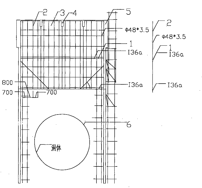
[0011] figure 1 It is a schematic diagram of erecting Mantang scaffolding according to the specific embodiment of the present invention. Among them, 1 is pre-embedded I36a I-beam, 2 is full scaffolding ф48*3.5 steel pipe, 3 is the main girder of the cast-in-place roof with a cross-sectional size of 1400*350, and 4 is the secondary beam of the cast-in-place roof with a cross-sectional size of 900*300 , 5 is the cast-in-place shear wall, 6 is the built-in equipment, with a diameter of 7.860m, ​​a length of 26.040m, and a central elevation of 5.800m.

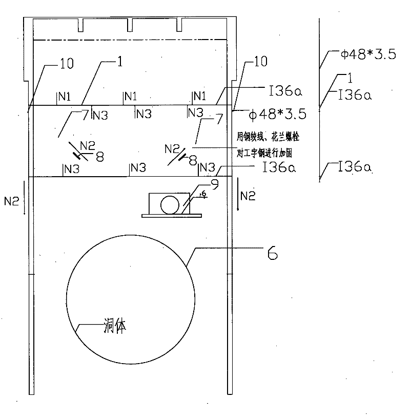
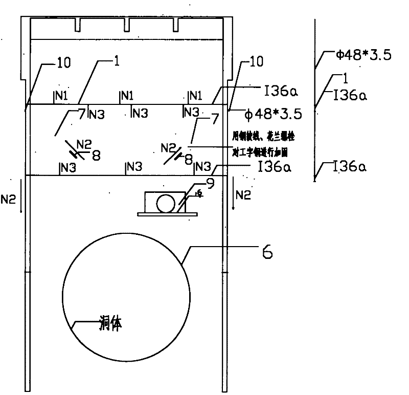
[0012] figure 2 It is a schematic diagram of the unloading and measurable and controllable process implementation of the I-beam in the specific embodiment of the present invention. Among them, 1 is pre-embedded I36a I-beam, 6 is built-in equipment, diameter 7.860m, ​​length 26.040m, center elevation 5.80...


PUM


Abstract

The invention relates to a construction method for a large-span cast-in-situ beam slab support system of a plant, which is characterized in that a middle part and an upper part of a shear wall are respectively buried with I-shaped steel to stretch over a room, and a pull ring 9 is welded on the one-third, a cross part, of the middle I-shaped steel 1 for obliquely drawing a steel wire rope 7 between wall bodies, a roof full scaffold is supported on two layers of the I-shaped steel 1 to unload the I-shaped steel 1 through obliquely drawing the I-shaped steel 1 and the steel wire rope 7 between the shear walls with a turnbuckle 8, and the forced deformation of the support system is measured and controlled by measuring the deformation of the I-shaped steel 1 in the concrete casting and loading process. The embodiment scheme of the construction method is that the settlement deformation of the I-shaped steel 1 in different loading stages can be measured through a leveling instrument in the process of the concrete casting and loading process, if the deformation exceeds a preset limit value, the I-shaped steel is unloaded through fastening the turnbuckle 8 to strain the steel wire rope 7,so as to prevent the deformation from exceeding the preset limit value, and the loading deformation value of the support system can be continuously kept in the limit value range through circulating operation, thereby achieving the effective measureable and controllable effect.

Description

technical field [0001] The invention belongs to the construction technology of a large-span beam-slab support system for a factory building structure, and in particular relates to the construction of a cast-in-place beam-slab support system for a single-storey factory building under the condition that the storey height is super high and the span is large, and it is impossible to support a full scaffolding by conventional methods method. Background technique [0002] In general factory buildings, the storey height is not high, and there is no equipment influence in the main construction of the civil works. The beam and slab support of the upper structure can be carried out by erecting full scaffolding on the ground or floor support. This method is simple to support, but it has great impact on the support system. Force deformation cannot be measured and controlled. In this project, because the built-in equipment is installed first and then the main body of the civil enclosure...

Claims


Application Information

Patent Timeline
Patent Type & Authority Patents(China)
IPC IPC(8): E04G13/04E04G25/02
Inventor 李博平杨辉
Owner 中国人民解放军63926部队
Why Eureka
Try Eureka