Exhaust gas purification system for diesel engines

A technology for diesel engine and exhaust gas purification, applied in engine components, combustion engines, machines/engines, etc., can solve problems such as space problems, achieve compact structure, improve rapid gasification, and large degrees of freedom.

Active Publication Date: 2011-08-24
EMITEC EMISSIONSTECHNIK
View PDF4 Cites 14 Cited by
  • Summary
  • Abstract
  • Description
  • Claims
  • Application Information

AI Technical Summary

Problems solved by technology

For this purpose, a catalytic converter should also be arranged in the exhaust system, where, especially for commercial vehicles, the (larger) exhaust gas volumes generated can cause space problems when integrating (integrating) a relatively large-volume converter

Method used


Image

  • Exhaust gas purification system for diesel engines
  • Exhaust gas purification system for diesel engines

Examples


Embodiment Construction

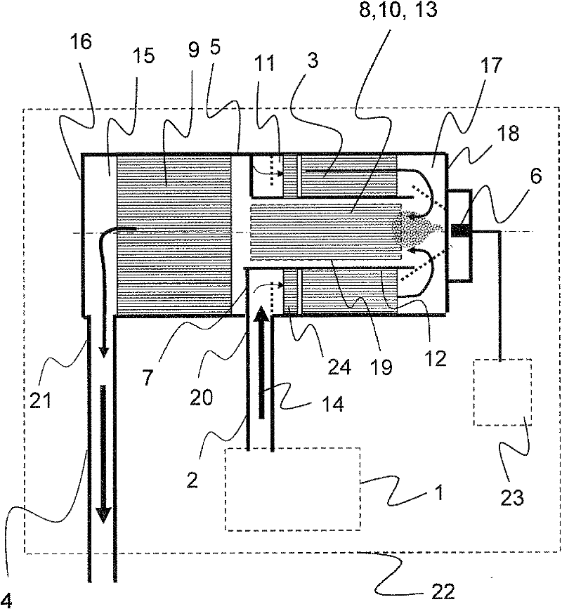
[0027] exist figure 1 The exhaust gas purification system shown in is used in particular for diesel engines of commercial vehicles. The power requirements of commercial vehicles are very high, while at the same time the consumption should be as low as possible. Carbon dioxide and water vapor are mainly produced during fuel combustion in each cylinder of a diesel engine, but the incomplete combustion makes unburned hydrocarbons, carbon monoxide, carbon black, and nitrogen oxides formed due to high combustion temperatures still exist in the exhaust substances, which are to be removed from the exhaust gas as completely as possible by means of the exhaust gas purification system according to the invention.

[0028] according to figure 1 The diesel engine 1 is connected to the casing 5 of the exhaust gas purification system through the exhaust pipe 2 . The exhaust pipe 2 opens approximately centrally on the outer circumference of the housing 5 into the region of the partition wa...


PUM


Abstract

The invention relates to an exhaust gas purification system for diesel engines (1), wherein at least one oxidation catalyst (3), a reducing agent injection device (6) and a reduction catalyst (9) are provided, which are arranged together in a housing (5) having a first lateral chamber (15) close to a first face (16) and a second lateral chamber (17) close to a second face (18), wherein: - the reduction catalyst (9) is arranged in the first lateral chamber (15), - the oxidation catalyst (3) is arranged in an outer annular space (11) of the second lateral chamber (17), - the reducing agent injection device (6) is oriented toward an inner channel (19) of the outer annular space (11) of the second lateral chamber (17), and - a flow path (14) for the exhaust gas from at least one exhaust gas inlet (20) toward at least one exhaust gas outlet (21) is provided, through the following components: oxidation catalyst (3), reducing agent injection device (6), and reduction catalyst (9).

Description

technical field [0001] The invention relates to an exhaust gas purification system for a diesel engine, in particular a commercial vehicle, comprising exhaust gas purification components arranged in the exhaust line, such as oxidation catalytic (converter), reducing agent injection / injection device, carbon black / soot particle separator, reduction catalyst (conversion) device. Background technique [0002] In the field of exhaust gas treatment of mobile internal combustion engines, catalytic converters and soot particle separators in the form of honeycomb bodies with channel-forming, structured carrier elements (in particular sheet metal, wire non-woven fabrics etc., or ceramic plates, extrudates...), wherein the structure of the carrier element can be given a microstructure which forms openings and flow-guiding surfaces which The partial flow of exhaust gas is directed along the carrier element from the inside to the outside and / or from the outside to the inside. [0003]...

Claims


Application Information

Patent Timeline
Patent Type & Authority Applications(China)
IPC IPC(8): F01N3/20F01N3/28
CPCF01N2013/026F01N2610/02F01N2470/24Y02T10/24F01N2470/18F01N3/0231F01N2490/06F01N3/035F01N2240/16F01N3/2066F01N3/2839F01N2240/40F01N13/0097Y02T10/12
Inventor K·米勒-哈斯
Owner EMITEC EMISSIONSTECHNIK
Why Eureka
Try Eureka