Grease removal apparatus, systems and methods

A filter assembly and manufacturing method technology, applied in membrane filters, chemical instruments and methods, separation methods, etc., can solve the problems of insufficient baffles to remove grease, poor effect, etc., to achieve protection and cleanliness and avoid burning damage. Effect

Inactive Publication Date: 2011-08-24
CLEAN SYST
View PDF8 Cites 17 Cited by
  • Summary
  • Abstract
  • Description
  • Claims
  • Application Information

AI Technical Summary

Problems solved by technology

However, UL Standard 1046 does not adequately address the effectiveness of baffles in actually removing grease from the airflow and preventing it from entering the exhaust pipe
As a result, most baffles are poor at removing grease from the airflow

Method used


Image

  • Grease removal apparatus, systems and methods
  • Grease removal apparatus, systems and methods
  • Grease removal apparatus, systems and methods

Examples


Embodiment Construction

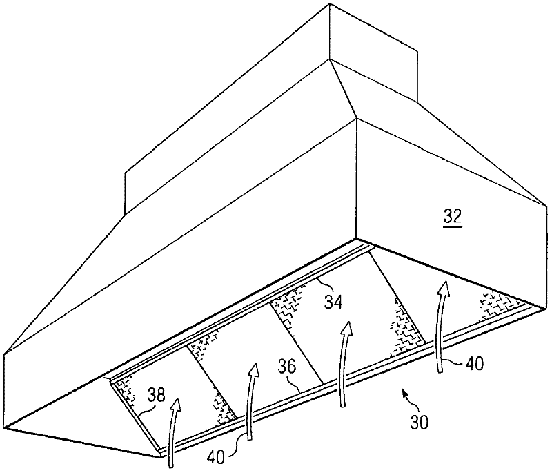
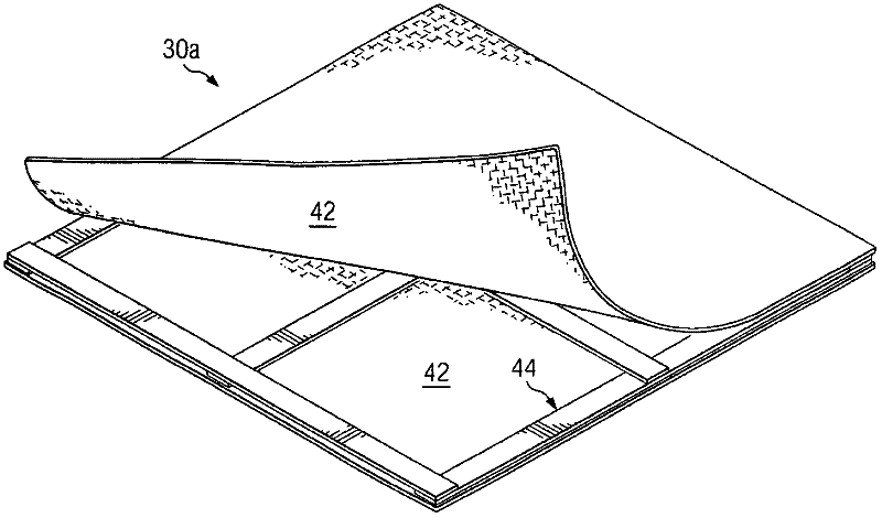
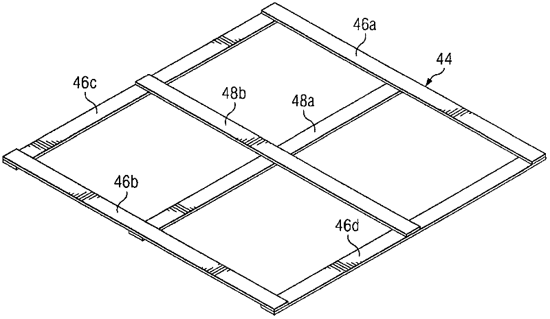
[0034] The present invention relates to grease removal equipment, systems and methods. Particular embodiments of the present invention include a filter assembly, which may be referred to herein as a replaceable grease removal device ("DGRD"), and may be used, for example, in a cooking room exhaust system. In particular embodiments, the DGRD may be formed of materials such that it is substantially "self-supporting," ie, it does not require a metal filter support frame, frame cover, or heat shield. DGRDs can be formed from various materials and in various ways, making them recyclable or disposable. In these embodiments, the DGRD may be conveniently mounted within the hood by simply sliding the DGRD into place on a bracket or by some other similar fastening means or support system within the hood.

[0035] Figure 1-3 DGRD 30 of a particular embodiment is shown in more detail. DGRD 30 is mounted within exhaust hood 32 . Exhaust hood 32 is constructed and arranged so that air ...


PUM

PropertyMeasurementUnit
thicknessaaaaaaaaaa
thicknessaaaaaaaaaa

Abstract

A filter assembly includes a filter pad comprising fibers including natural, synthetic and/or hybrid fibers. A stabilizer frame formed of a non-metallic material may be imbedded in the filter pad. The stabilizer frame may be configured to provide support to the filter pad to maintain the filter pad in a generally flat configuration. In accordance with a particular embodiment, the filter pad may be comprised of at least first and second fibrous mats that are coupled together. In this embodiment, the stabilizer frame may be disposed between and coupled with the first and second fibrous mats.

Description

technical field [0001] The technology of the present invention relates to the field of exhaust filtration in ventilation systems, in particular to grease removal equipment, systems and methods. Background technique [0002] In cook rooms, grease filters and / or grease removers are often installed in exhaust hoods above various cooking appliances that generate excessive heat and flames, including deep fryers, grills, frying pans and ovens . In applications using existing wool or fiber based filters (see eg US Patent 6,293,983), excess heat or flames can cause problems. Unless a stainless steel heat shield is placed in front of the wool filter, there is a possibility that concentrated heat (eg, exhaust from a cooking appliance) will degrade the wool fibers and cause holes to form in the filter. Similarly, if the flame is in direct contact with the filter (which can happen over grills and pans in the case of fat burning), the flame will create holes in the filter. This is a v...

Claims


Application Information

Patent Timeline
Patent Type & Authority Applications(China)
IPC IPC(8): F24C15/20
CPCB01D46/10B01D39/1615D04H1/04B01D39/163F24C15/2035D04H1/48B01D2239/065Y10T29/49885Y10T29/49826Y10T29/49B01D46/0001B23P11/00B01D39/1607B01D46/0093
Inventor 格伦·大卫·亚历山大约瑟夫·安东尼·塞尔彼得拉
Owner CLEAN SYST
Why Eureka
Try Eureka