Airlift-jet multi-stage loop reactor

A loop reactor and jet technology, applied in the field of reactors, can solve the problems of high energy consumption and unsatisfactory gas-liquid distribution, and achieve the effects of low energy consumption, good mass transfer effect, and uniform gas-liquid distribution

Active Publication Date: 2011-08-31
TSINGHUA UNIV
View PDF4 Cites 9 Cited by
  • Summary
  • Abstract
  • Description
  • Claims
  • Application Information

AI Technical Summary

Problems solved by technology

However, for the gas-liquid reactor system, if the jet is used alone, the energy consu

Method used


Image

  • Airlift-jet multi-stage loop reactor
  • Airlift-jet multi-stage loop reactor
  • Airlift-jet multi-stage loop reactor

Examples


Embodiment 1

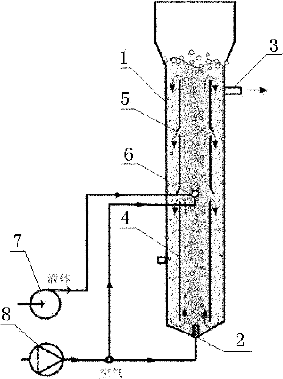
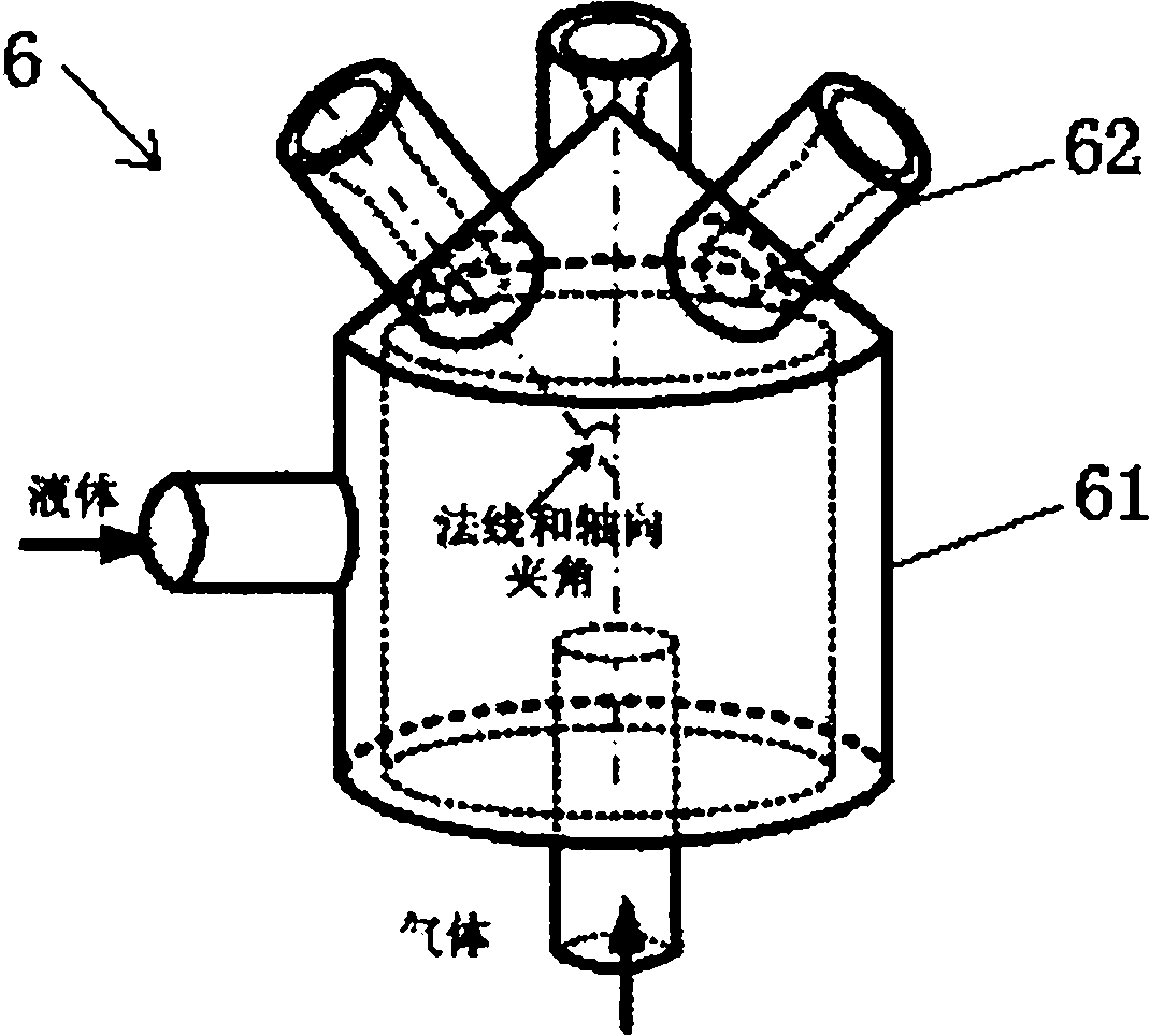
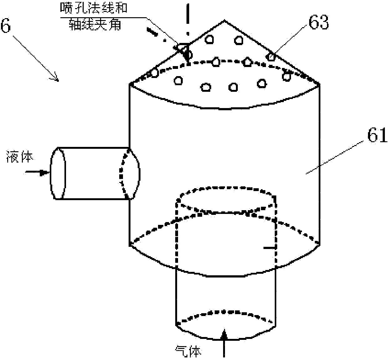
[0029] Embodiment 1: This embodiment is the hydrodynamic conditions in a 180L airlift-jet multi-stage loop reactor. The tower body 1 has a height of 3000mm and a diameter of 280mm. The diameter of the guide tube 4 is 213mm, and there are 3 sections in total, with a total height of 2130mm. The heights of each section of the guide tube 4 from bottom to top are 900mm, 400mm and 750mm in turn, and the gap between the adjacent sections of the guide tube 4 is 40mm . The distance between the lower edge of the guide tube 4 and the bottom of the tower body 1 is 100mm. The jet distributor 6 adopts such as figure 2 The shown form is installed in the first gap (H=940mm) at the lowermost end, and is composed of three nozzles with a diameter of 5mm, and the initial shot direction of the nozzles and the axis angle of the tower body 1 are 45 °. The total air flow injected into the tower body 1 is 100L / min (working condition, the same below), wherein, the air flow of the tower bottom gas d...

Embodiment 2

[0030] Embodiment 2: This embodiment is the influence of jet gas volume and liquid volume on jet effect. The settings and specifications of the tower body 1 and the guide tube 4 are the same as those in Example 1, and the experimental system is water-air. The total amount of gas injected into the tower body 1 is 100min / L (operating conditions, the same below), the liquid volume (L) is 24L / min, and the gas volume (V G1 ) and the gas volume injected by the jet distributor 6 (V G2 ) ratio V G1 :V G2 , and the ratio of jet liquid to gas volume L:V G2 At different times, the measured apparent circulation liquid velocity and volumetric gas holdup are shown in Table 1. In the control group, except that there was no jet flow, other conditions were the same, and the measurement results were as follows: Image 6 shown. Visible V G1 :V G2 In the range of 1:1~3:1, L:V G2 In the range of 1:3 to 1:1, the circulating liquid velocity and the volumetric gas holdup are increased to var...

Embodiment 3

[0033] Embodiment 3: This embodiment is the influence of the position of the jet and the angle of the first shot on the effect of the jet. The settings and specifications of the tower body 1 and the guide tube 4 are the same as those in Example 1, and the experimental system is water-air. Introduce the jet flow in the first gap (the plane where the nozzle is located from the lower edge of the draft tube height H=940mm) and the second gap (H=1380mm) from bottom to top of the draft tube 4 respectively. The total amount of gas injected into the tower body 1 is 100min / L (operating conditions, the same below), wherein the ventilation rate of the gas distributor 2 at the bottom of the tower is 60L / min, the ventilation rate of the jet distributor 6 is 40L / min, and the liquid The volume is 24L / min. The control group was under the same conditions except for no jet flow. The measurement results are shown in Table 2. It can be seen that the height of the jet flow position is within the ...


PUM


Abstract

The invention relates to an airlift-jet multi-stage loop reactor, which is characterized in that the reactor comprises a tower body, the bottom of the tower body is provided with a tower-bottom gas distributor, the inside of the tower body is provided with a guide cylinder divided into a plurality of segments, and a jet distributor is arranged in a clearance between each two adjacent segments of the guide cylinder; and the outside of the tower body is provided with a liquid pump and a gas compressor, one end of the liquid pump is connected with a liquid source by a pipe, and the other end of the liquid pump is connected with the jet distributor by a pipe, one end of the gas compressor is connected with a gas source by a gas input pipe, and the other end of the gas compressor is respectively correspondingly connected with the jet distributor and the tower-bottom gas distributor by two gas output pipes. By using the airlift-jet multi-stage loop reactor disclosed by the invention, the fluid is driven to carry out circulatory flow along the guide cylinder under the action of airlift and jet, therefore, the loop driving force and the local disturbance are increased, so that the mass transfer coefficient and the mass transfer specific surface area are significantly increased, and to the high-viscosity fluid, a high loop liquid velocity and a good mass transfer effect still can be obtained, therefore, the airlift-jet multi-stage loop reactor disclosed by the invention has a broad application prospect in gas-liquid two-phase or gas-liquid-solid three-phase chemical and biological reaction fields.

Description

technical field [0001] The invention relates to a reactor applied in the field of chemical and biological reaction engineering, in particular to an air-lift-jet multi-stage circulation for high-viscosity gas-liquid two-phase or gas-liquid-solid three-phase reaction or separation reactor. Background technique [0002] The air-lift loop reactor developed based on the bubble reactor is to add an internal member guide tube in the bubble reactor to make the fluid circulate around the guide tube in the reactor, so as to realize the gas, liquid The three phases of solid and solid are uniformly mixed to obtain a higher mass transfer coefficient between phases. It is widely used in many gas, liquid and solid three-phase reactions such as biological fermentation process and sewage treatment process, as well as gas and liquid reaction and separation process. [0003] In the traditional air-lift loop reactor, the bubbles continue to coalesce and become larger during the rising process...

Claims


Application Information

Patent Timeline
IPC IPC(8): B01J8/08B01J10/00B01J19/24
Inventor 蒋国强王于杰唐世福丁富新
Owner TSINGHUA UNIV
Why Eureka
Try Eureka