Crankcase structure

A crankcase and crankshaft technology, applied in the direction of engine cooling, engine lubrication, gear lubrication/cooling, etc., can solve the problems of oil return lag, friction increase, weight increase, etc., to suppress weight increase and oil pressure Change, apply the appropriate effect

Inactive Publication Date: 2011-08-31
HONDA MOTOR CO LTD
View PDF7 Cites 13 Cited by
  • Summary
  • Abstract
  • Description
  • Claims
  • Application Information

AI Technical Summary

Problems solved by technology

[0005] Therefore, there are problems in that the weight increases, and if the oil overflows into the crank chamber, since the crank arm of the crankshaft is immersed in the oil, the friction increases with the rotation of the crankshaft
[0014] However, in the above-mentioned Patent Document 1, when the internal combustion engine is greatly tilted, especially when the internal combustion engine is tilted front, rear, left, right, or accelerated or decelerated along with the vehicle body, since the oil level in the oil pan will tilt at this time, Therefore, the oil tends to move to the upper side of the lower partition wall and the upper partition wall at the front and back, and the oil level of the oil pan is significantly lowered, and the oil suction port may be exposed.
Also, the return of oil that has moved to the bulkhead or between the crankcase and the crankcase cover, etc. outside the oil pan due to the temporary inclination of the oil surface will be delayed.
On the other hand, in order to prevent the oil suction po...

Method used


Image

  • Crankcase structure
  • Crankcase structure
  • Crankcase structure

Examples


Embodiment Construction

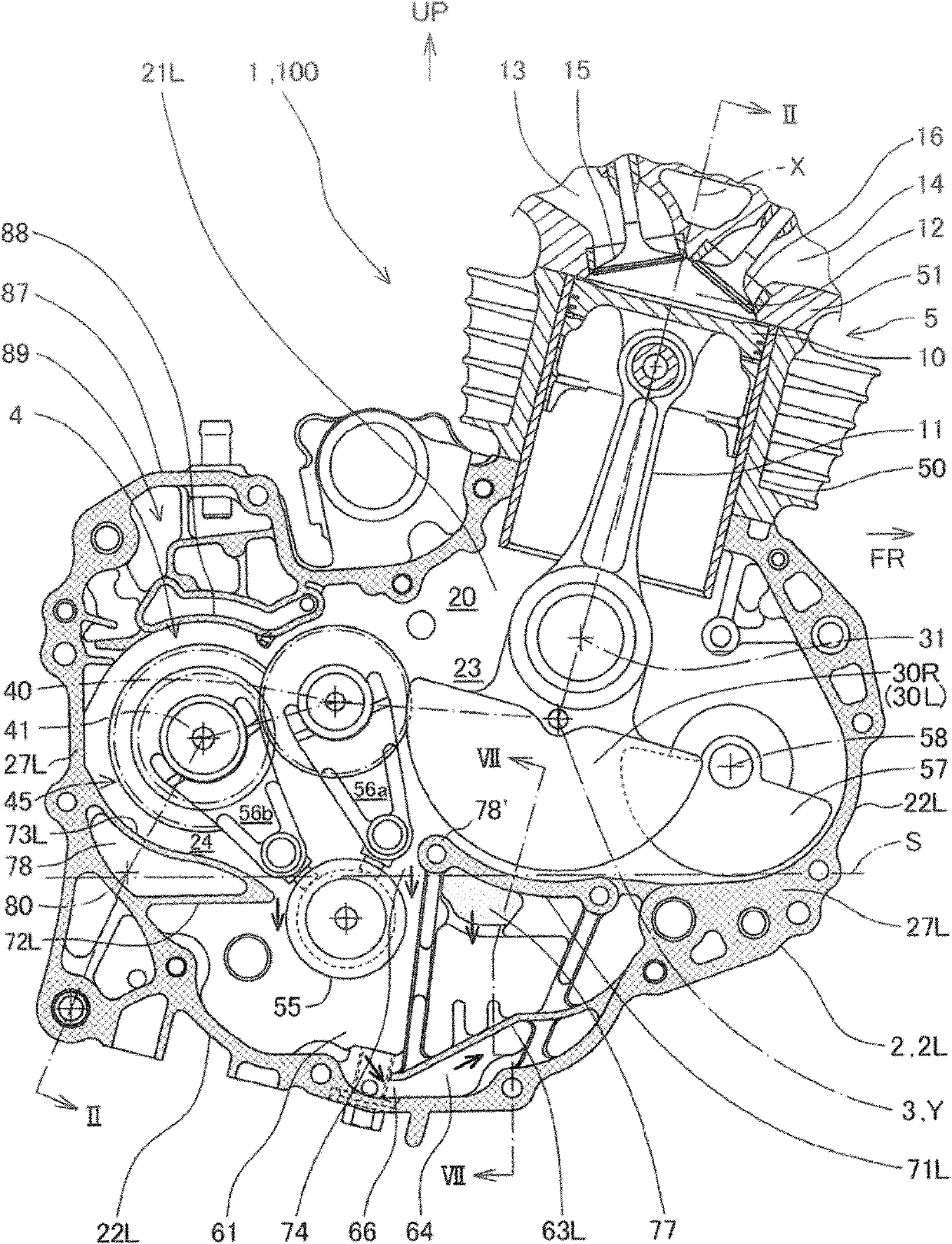
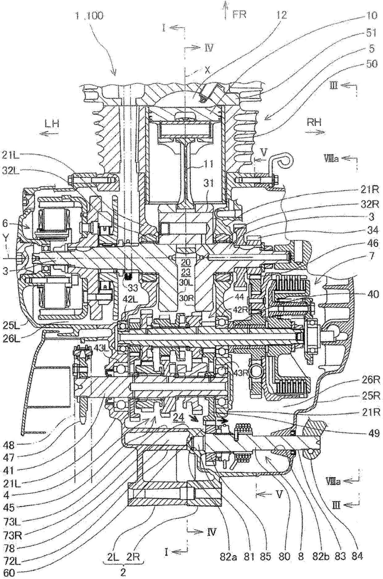
[0050] Below, based on Figure 1 to Figure 11 The crankcase structure of the first embodiment of the present invention will be described.

[0051] In the present specification and claims, directions such as front, rear, left, right, up and down correspond to the direction of the vehicle when the internal combustion engine of the present embodiment is mounted on a vehicle such as a motorcycle. In the figure, arrow FR indicates the front of the vehicle, LH indicates the left side of the vehicle, RH indicates the right side of the vehicle, and UP indicates the upper side of the vehicle.

[0052] In addition, the small arrows attached to the devices and structural parts in each figure schematically indicate the flow direction of lubricating oil.

[0053] The internal combustion engine 1 of the present embodiment is a single-cylinder four-stroke internal combustion engine. In a vehicle not shown, such as a motorcycle, the internal combustion engine 1 is arranged such that the cran...


PUM


Abstract

The invention provides a crankcase structure, which inhibits the change and descending of oil level in the bottom of the casing due to the inclination of an internal combustion engine and enables the oil to rapidly return for preventing the exposure of an oil-sucking opening and preventing an oil pump from generating cavitation. In a supporting crankshaft (3) and a speed changer (4) and a crankcase (2) of an internal combustion engine (1) having an oil sump (61) at the bottom, an oil-sucking opening (66) which sucks the oil in the oil sump (61) through an oil pump (62) is disposed at the bottom of the oil sump (61). The crankcase (2) comprises an oil return port (74) which enables the oil of a lubricating crankshaft (3) or the speed changer (4) to return to the oil sump (61), separating walls (71L, 71R) for separating the crankshaft (3) and the oil sump (61) or separating walls (72L, 72R) for separating the speed changer (4) and the oil sump (61), and oil discharging parts (78, 78') which are connected to the separating walls and are at least partially disposed at the upper part of the oil surface when the internal combustion engine storing proper amount of oil stops.

Description

technical field [0001] The invention relates to a crankcase structure of an internal combustion engine. The crankcase is composed of an oil pan under the crankcase and an oil suction port at the bottom of the oil pan. Background technique [0002] An internal combustion engine provided with an oil pan below the crankcase includes a lubricating system that draws oil stored in the oil pan and supplies it to lubricating parts that require lubrication. In the oil pumping mechanism of this lubrication system, the oil suction port is placed close to the bottom surface of the oil pan, and the oil suction port is always completely immersed in the oil in order not to be affected by the amount of oil stored in the oil pan, so as to avoid Inhale air. [0003] If air is sucked in, the output oil pressure of the oil pump will fluctuate due to cavitation (エア㙛み), and oil cannot be supplied to the lubricated part at a stable oil pressure. [0004] Therefore, not only the oil suction port ...

Claims


Application Information

Patent Timeline
IPC IPC(8): F02F7/00F01M11/00F01P11/08F01M11/06F16H57/023F16H57/04
Inventor 高桥明山代隼人三木敏弘
Owner HONDA MOTOR CO LTD
Why Eureka
Try Eureka