Battery protecting device and protecting method

A battery protection device and discharge control technology, applied in emergency protection circuit devices, circuit devices, emergency protection circuit devices for limiting overcurrent/overvoltage, etc. , battery pole piece carbonization and poor contact, etc., to achieve the effect of prolonging storage time, suppressing transient high current, and preventing fire from hurting people

Active Publication Date: 2014-02-12
HYTERA COMM CORP
View PDF5 Cites 0 Cited by
  • Summary
  • Abstract
  • Description
  • Claims
  • Application Information

AI Technical Summary

Problems solved by technology

For example, there is a battery using the above-mentioned current-limiting protection scheme. The discharge output current limit set by the circuit is 3A. The instantaneous peak current can reach 15A (see figure 2 )
[0008] It can be seen that the defect of the existing battery discharge protection device is that since the external power supply switch of the battery is always on, the discharge output port of the battery will have a current output as long as it is connected to a load. If the output is short-circuited suddenly, it is easy to cause fire and hurt people accident
And the fire accident makes the battery pole piece prone to carbonization and poor contact, which affects the service life of the battery pole piece, thus affecting the reliability of electronic products

Method used


Image

  • Battery protecting device and protecting method
  • Battery protecting device and protecting method
  • Battery protecting device and protecting method

Examples


no. 1 example

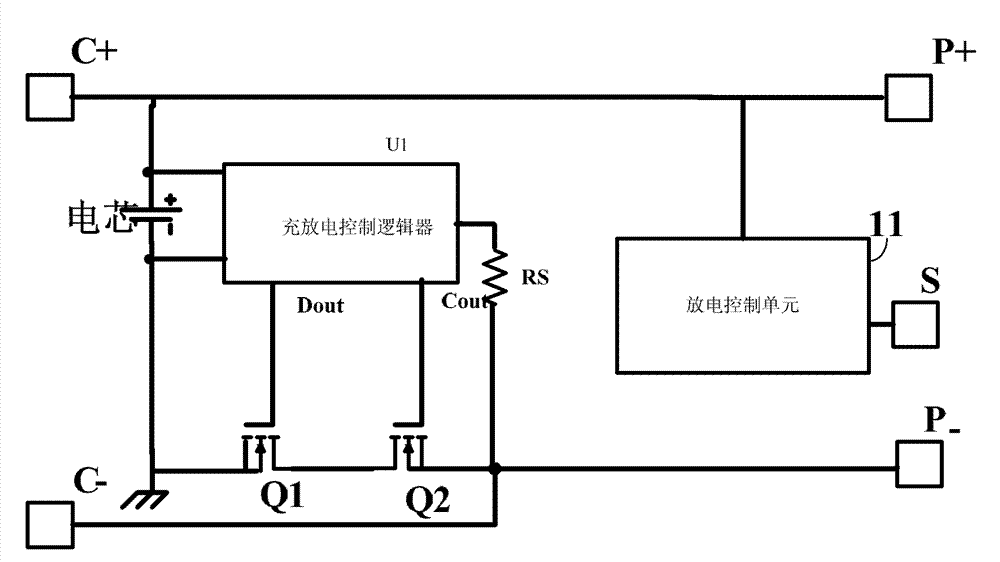
[0035] see Figure 4, shows the first embodiment of the battery protection device of the present invention, which includes a charge and discharge control logic U1, one end of the charge and discharge control logic U1 is connected to the negative electrode C- of the battery charging port through a resistor RS, and one output end of the charge and discharge control logic U1 is connected to the discharge terminal. The gate of MOS transistor Q1, the other output end is connected to the gate of charging MOS transistor Q2; the source of discharging MOS transistor Q1 is connected to the negative pole of the cell, the drain is connected to the source of charging MOS transistor Q2, the positive pole of the discharge port P+, and the charging port The positive pole C+ is connected to the positive pole of the cell;

[0036] It also includes a feedback terminal S connected to the positive pole P+ of the discharge port. The discharge control unit 11 includes a MOS transistor Q3, a MOS tran...

no. 2 example

[0041] see Figure 5 , shows the second embodiment of the battery protection device of the present invention, including a charge and discharge control logic U1, one end of the charge and discharge control logic U1 is connected to the negative pole P- of the battery discharge port through a resistor RS, and one output end of the charge and discharge control logic U1 is connected to the discharge port The gate of the MOS transistor Q1, and the other output terminal is connected to the gate of the charging MOS transistor Q2; the source of the discharging MOS transistor Q1 is connected to the negative pole of the cell, the drain is connected to the source of the charging MOS transistor Q2, and the positive pole of the discharge port P+ is connected to the battery. the positive pole of the core;

[0042] It also includes a feedback terminal S connected to the positive pole P+ of the discharge port. The discharge control unit 11 includes a MOS transistor Q3 and a MOS transistor Q4. ...

no. 3 example

[0046] see Image 6 , shows the third embodiment of the battery protection device of the present invention, including a charge and discharge control logic U1, one end of the charge and discharge control logic U1 is connected to the negative pole P- of the battery discharge port through a resistor RS, and one output end of the charge and discharge control logic U1 is connected to the discharge port The gate of the MOS transistor Q1, and the other output terminal is connected to the gate of the charging MOS transistor Q2; the source of the discharging MOS transistor Q1 is connected to the negative pole of the cell, the drain is connected to the source of the charging MOS transistor Q2, and the positive pole of the discharge port P+ is connected to the battery. the positive pole of the core;

[0047] It also includes a feedback terminal S connected to the positive pole P+ of the discharge port. The discharge control unit 11 includes a MOS transistor Q5, the source of the MOS tran...


PUM


Abstract

The invention relates to a battery protecting device, comprising a charge-discharge control logic device, a feedback end and a discharge control unit, wherein one output end of the charge-discharge control logic device is connected with the grid electrode of a first MOS (metal oxide semiconductor) tube, and the other output end of the charge-discharge control logic device is connected with the grid electrode of a second MOS tube; the source electrode of the first MOS tube is connected with the earth, the drain electrode of the first MOS tube is connected with the source electrode of the second MOS tube, and the drain electrode of the second MOS tube is connected with the negative electrode of a discharge port; one end of the discharge control unit is connected with the feedback end, and one end of the discharge control unit is connected with the discharge port; the feedback end is used for obtaining a feedback voltage when a battery is connected with a load; the discharge control unit is used for controlling a discharge switching tube to delay breakover when the feedback voltage is obtained in the feedback section; and a breakover electric resistance of the discharge switching tube is changed from high to low, so that a battery discharge current is applied to the load. The invention also provides a battery protecting method. With the device and the method, a transient heavy current is effectively restrained, and the accident of striking a light to hurt a person is avoided, so that the safety of using the battery is enhanced.

Description

technical field [0001] The invention relates to the field of electronic circuits, in particular to a battery protection device and a protection method. Background technique [0002] The general rechargeable battery protection scheme is that the cell voltage is output to the load through two series-connected charge switches and discharge switches. If the cell voltage is within the range set by the battery protection chip, the charge switch and discharge switch are always on. A large current can be exported at any time. Since the pole piece of the battery is exposed in the air, it is easy to be touched by external conductive objects. When there is a conductor short circuit between the positive and negative pole pieces of the discharge output terminal of the battery, the battery will output a large current instantly, which will cause the pole piece to ignite, which is easy Accidents causing fire or burns. [0003] Rechargeable batteries are used in handheld electrical applian...

Claims


Application Information

Patent Timeline
Patent Type & Authority Patents(China)
IPC IPC(8): H02H9/02H02H7/18
Inventor 熊运远潘启辉卢良飞
Owner HYTERA COMM CORP
Why Eureka
Try Eureka