Microlithographic projection exposure apparatus

A technology of microlithography and equipment, applied in the field of lighting systems and projection objective lenses, which can solve the problems of inability to guarantee heat dissipation and damage to components

Active Publication Date: 2011-08-31
CARL ZEISS SMT GMBH
View PDF6 Cites 10 Cited by
  • Summary
  • Abstract
  • Description
  • Claims
  • Application Information

AI Technical Summary

Problems solved by technology

The light absorbed by the mirrors heats them up, which can lead to destruction of the reflect

Method used


Image

  • Microlithographic projection exposure apparatus
  • Microlithographic projection exposure apparatus
  • Microlithographic projection exposure apparatus

Examples


Embodiment Construction

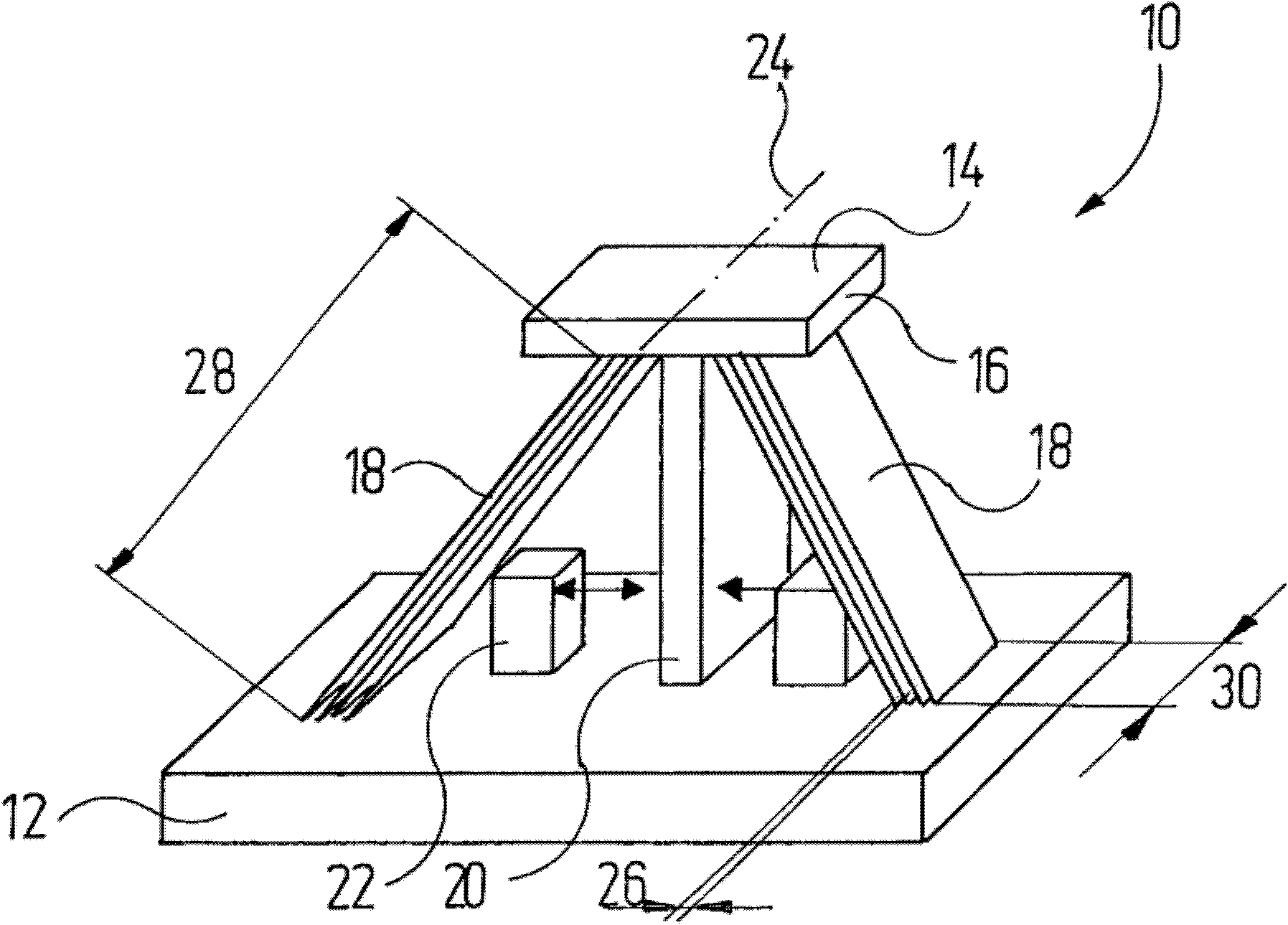
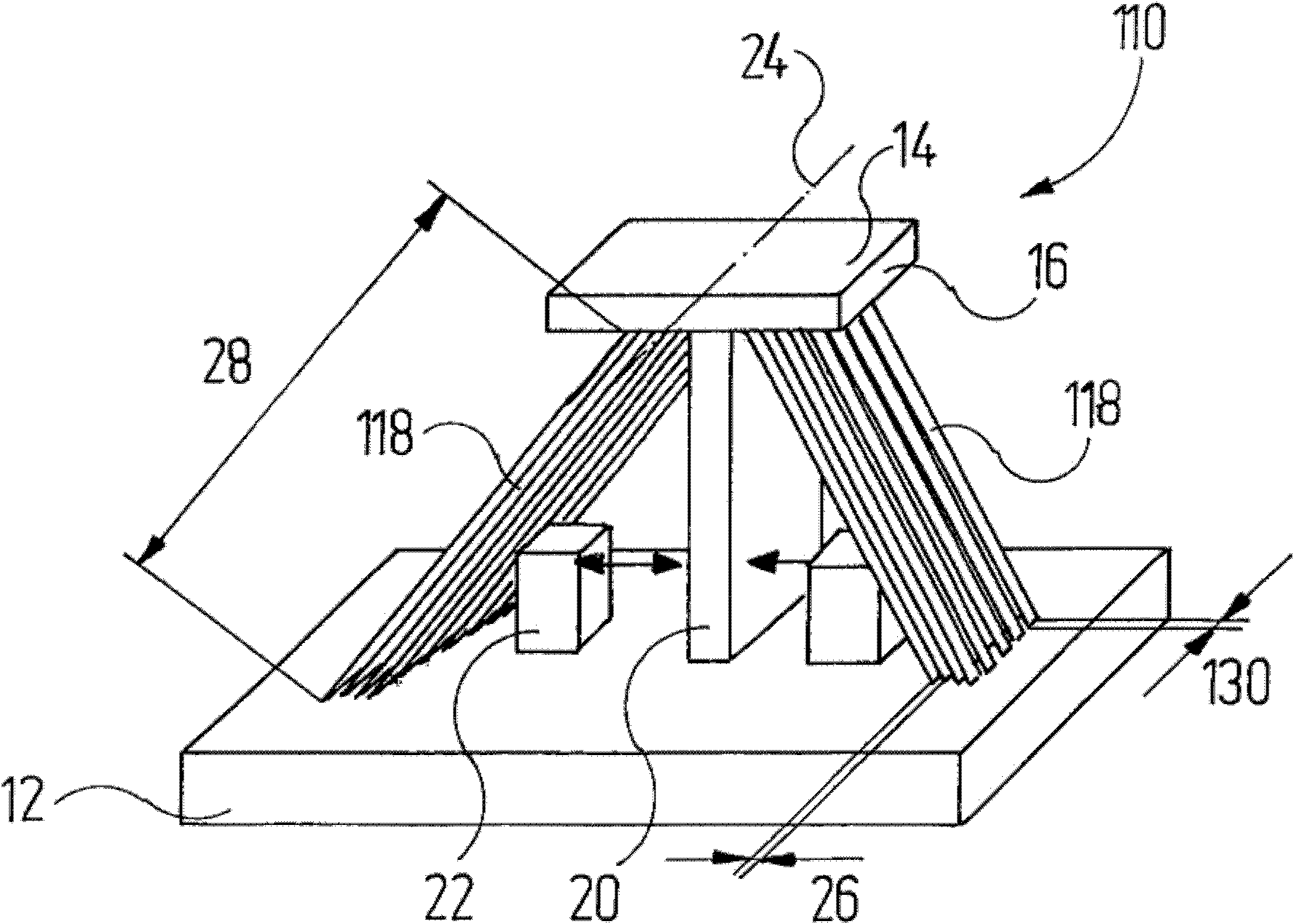
[0085] figure 1 A perspective view showing a detail of a mirror unit 10 included in an illumination system of a projection exposure apparatus for microlithography. The details shown reveal a base plate 12, a mirror unit with a mirror 14, and two sets of leaf springs 18, the mirror 14 being held on a T-shaped support 16, and two sets of leaf springs 18 connected to the support 16 and the base plate 12 and is constructed of a material with high thermal conductivity such as steel, silicon, silicon carbide, copper, silver or gold. The leaf spring 18 together with the support body 16 forms a solid joint for the mirror 14 .

[0086] The mirror unit also has two magnetic coils 22 arranged between the leaf spring 18 and the longer branch of the support body 16 . Of course, other drives can also be used instead of magnetic coils. The mirror unit includes figure 1 A plurality of mirror units are shown, for example hundreds or even thousands, arranged on a common base plate 12 . The...


PUM


Abstract

A microlithographic projection exposure apparatus has a mirror array having a base body and a plurality of mirror units, each of which comprises a mirror and a solid-state articulation, which has at least one articulation part that connects the mirror to the base body. A control device makes it possible to modify the alignment of the respective mirror relative to the base body. Mutually opposing surfaces of the mirror and of the base body, or of a mirror support body connected to it, are designed as corresponding glide surfaces of a sliding bearing.

Description

technical field [0001] The present invention relates to a microlithographic projection exposure apparatus, in particular to an illumination system and a projection objective of such an arrangement having a mirror array with a substrate and a plurality of mirrors arranged on the substrate and the plurality of reflectors The mirrors can be tilted or otherwise altered in their arrangement relative to the substrate. Background technique [0002] Integrated circuits and other microstructured elements are typically fabricated by applying multiple structural layers to a suitable substrate, which may be a silicon wafer, for example. To structure these layers, they are first covered with a photoresist that is sensitive to light of a specific wavelength range, for example, light in the deep ultraviolet (DUV) or extreme ultraviolet (EUV) spectral range. Currently, conventional light wavelengths for DUV systems are 248nm, 193nm, and sometimes 157nm; EUV projection exposure equipment cu...

Claims


Application Information

Patent Timeline
IPC IPC(8): G03F7/20G02B26/08
CPCG02B7/1827G03F7/70116G02B26/0833G03F7/702G03F7/70291G03F7/70891G02B15/00G03F7/20H01L21/027G02B17/002
Inventor 萨沙·布莱迪斯特尔关彦彬弗洛里安·巴赫丹尼尔·本兹塞韦林·沃尔迪斯阿明·沃伯
Owner CARL ZEISS SMT GMBH
Why Eureka
Try Eureka