
Piezoelectric micro machining energy transducer

A transducer and piezoelectric technology, applied in the field of microelectronics, can solve problems that affect transducer performance, reduce transducer efficiency, and difficulties, and achieve the effect of improving electromechanical conversion efficiency, reducing complexity, and improving product performance

Inactive Publication Date: 2011-09-07
SHENZHEN UNIV
View PDF7 Cites 7 Cited by
  • Summary
  • Abstract
  • Description
  • Claims
  • Application Information

AI Technical Summary

Problems solved by technology

In order to improve the performance of the pMUT unit, many scholars have done a lot of work in structural design and processing technology, but have not achieved satisfactory results. The transducer based on pMUT is still not commercialized in terms of sensitivity and electromechanical coupling efficiency. Traditional transducers outperform
Optimizing the design can improve the performance of the transducer, but its effect is limited
In order to meet the application in the field of medical imaging, the operating frequency of the transducer needs to reach the order of MHz. Generally, the size of the diaphragm can be reduced to meet the requirements, but this will reduce the efficiency of the transducer.
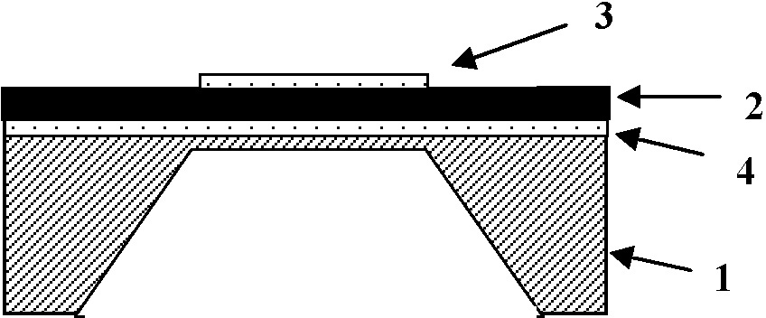
[0003] There are two main problems in the existing pMUT structure. One is the structure. Usually, the vibrating membrane is mainly composed of two parts, namely the piezoelectric layer and the non-piezoelectric layer. When the transducer works, the non-piezoelectric layer will It accounts for about half of the total kinetic energy. Since the non-piezoelectric layer has no piezoelectric effect and cannot convert kinetic energy into electrical energy, this part of energy is completely consumed. Second, in terms of technology, due to the piezoelectric layer and the non-piezoelectric layer The thickness and the proportional relationship between the two thicknesses are directly related to the electromechanical coupling coefficient and resonance frequency of the transducer, so in the micromachining process, it must be controlled very precisely. However, as far as the current technology is concerned, the two There are still some difficulties in the precise control of thickness
These unfavorable factors affect the performance of the transducer to a certain extent

Method used


Image

  • Piezoelectric micro machining energy transducer
  • Piezoelectric micro machining energy transducer
  • Piezoelectric micro machining energy transducer

Examples


Embodiment Construction

[0024] At first, explain the basic structure of the present invention:

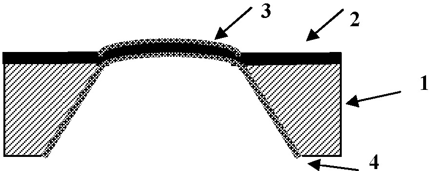
[0025] Such as figure 2 with 3 As shown, compared with the traditional pMUT unit, the single piezoelectric layer dome pMUT unit of the present invention does not have a silicon elastic layer in its vibration, and replaces the flat piezoelectric layer 2 with a dome. The upper electrode 3 and the lower electrode 4 are still provided on the surface of the piezoelectric layer 2 .

[0026] In the second step, the performance advantages of the present invention are described in detail by combining software simulation and experiments. The following structure one corresponds to the traditional pMUT structure and structure two corresponds to the single piezoelectric layer dome pMUT structure of the present invention:

[0027] (1) Displacement of the diaphragm center under DC voltage excitation

[0028] Such as Figure 4 As shown, for structure one, when the ratio of PZT (recommended to give the corresponding ...


PUM


Abstract

The invention relates to a piezoelectric micro machining energy transducer, which comprises a pore cavity and a vibrating membrane on the surface of the pore cavity, wherein the vibrating membrane consists of a piezoelectric layer (2), an upper electrode (3) on the upper surface of the piezoelectric layer (2) and a lower electrode (4) on the lower surface of the piezoelectric layer (2); and furthermore, the vibrating membrane protrudes outwards relative to the pore cavity. A single piezoelectric layer dome structure is adopted in the piezoelectric micro machining energy transducer, so that the electromechanical conversion efficiency and the product performance are greatly improved; meanwhile, the production process is simpler and more reliable.

Description

technical field [0001] The invention relates to microelectronic technology, in particular to a piezoelectric micromachining transducer, especially used in medical electronics. Background technique [0002] Piezoelectric micromachined ultrasonic transducer (pMUT) integrates piezoelectric thin / thick film technology and silicon micromachining technology, and uses the bending vibration mode of the diaphragm to transmit and receive ultrasonic waves. At present, the traditional pMUT basic unit has a structure such as figure 1 As shown, a vibrating membrane is provided on the quadrangular frustum-shaped cavity, which can basically be equivalent to a double-layer thin plate with peripheral fastening constraints, and one layer is a piezoelectric layer 2 (the upper and lower surfaces are respectively provided with upper electrodes 3 and The lower electrode 4 ), one layer is the silicon elastic layer extending from the silicon substrate 1 to the piezoelectric layer 2 . The electromec...

Claims


Application Information

Patent Timeline
IPC IPC(8): B06B1/06
Inventor 彭珏
Owner SHENZHEN UNIV
Learn More