Wind-power complementary pneumatic seawater desalting device

A wind power complementary, electric water pump technology, applied in wind power generation, seawater treatment, wind turbines, etc., to achieve the effect of high efficiency, alleviation of energy crisis, and reduction of energy conversion losses

Inactive Publication Date: 2011-09-07
吴速
View PDF5 Cites 11 Cited by
  • Summary
  • Abstract
  • Description
  • Claims
  • Application Information

AI Technical Summary

Problems solved by technology

[0003] For reverse osmosis seawater desalination, energy consumption is the key to directly determining its cost, and the power consumption of high

Method used


Image

  • Wind-power complementary pneumatic seawater desalting device
  • Wind-power complementary pneumatic seawater desalting device
  • Wind-power complementary pneumatic seawater desalting device

Examples


Embodiment 1

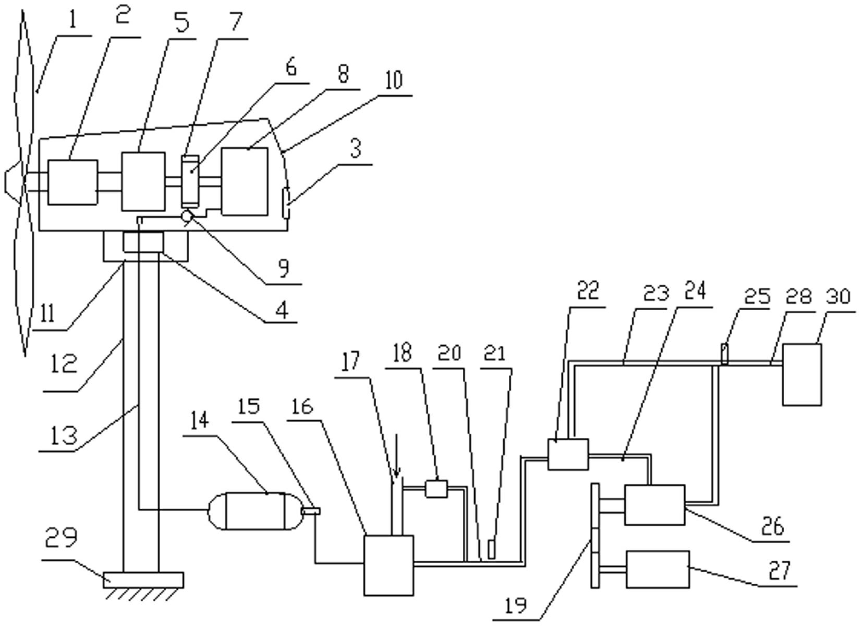
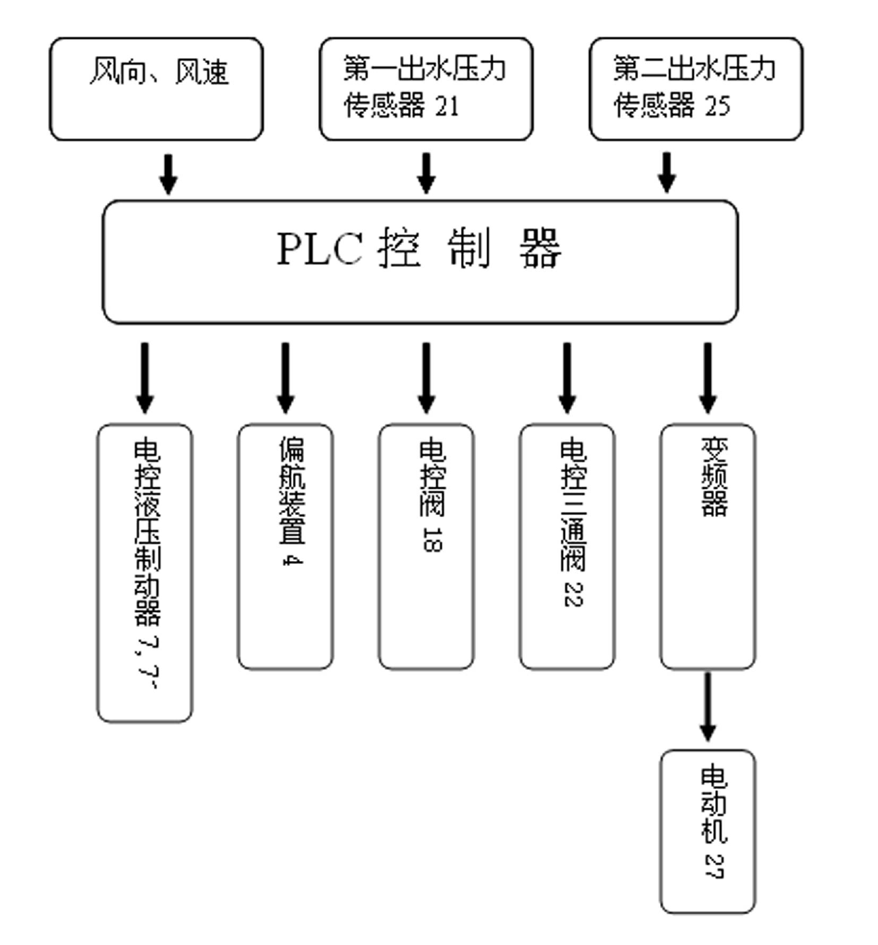
[0027] Such as figure 1 and image 3 As shown, it is a wind power complementary pneumatic seawater desalination device using a horizontal axis wind turbine impeller, including a pneumatic water pressure booster pump 16, an electric water pump 26, an air pipeline 13, and a wind-driven air compressor unit. The compressor unit includes a nacelle 10, an impeller 1 installed at the front of the nacelle 10, an impeller main shaft installed inside the nacelle 10, a supporting bearing 2 of the impeller main shaft, an acceleration gearbox 5, a coupling 6 and an air compressor 8, and the nacelle 10 The power transmission shafts inside are all connected by horizontal shafts.

[0028] The impeller main shaft is fixedly connected with the input shaft of the acceleration gearbox 5, and the output shaft of the acceleration gearbox 5 is fixedly connected with the main shaft of the air compressor 8 through a coupling 6, and the shaft coupling 6 An electronically controlled hydraulic brake 7 ...

Embodiment 2

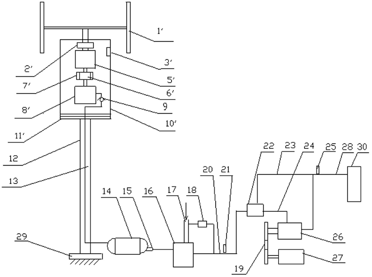
[0041] Such as figure 2 and image 3 As shown, it is a wind power complementary pneumatic seawater desalination device using a vertical axis wind turbine impeller, including a pneumatic water pressure booster pump 16, an electric water pump 26, an air pipeline 13, and a wind-driven air compressor unit. The compressor unit includes a nacelle 10', a wind turbine impeller 1' installed on the top of the nacelle 10', an impeller main shaft installed inside the nacelle 10', a support bearing 2' of the impeller main shaft, an acceleration gearbox 5', a coupling 6' and Air compressor 8 ', the power transmission shaft in its cabin all adopts vertical shaft connection. An air compressor inlet filter port 3' is provided on the nacelle 10'.

[0042] The main shaft of the impeller is fixedly connected with the input shaft of the acceleration gearbox 5', and the output shaft of the acceleration gearbox 5' is fixedly connected with the main shaft of the air compressor 8' through a couplin...


PUM


Abstract

The invention relates to the field of seawater desalinization, in particular to a wind-power complementary pneumatic seawater desalting device, which comprises a pneumatic water pressure booster pump, an electric water pump, a gas pipeline and a wind-driven air compressor unit. The air compressor unit comprises a cabin, a wind turbine impeller mounted in the front part of the cabin, and an impeller main shaft, an accelerating gearbox, a coupler and an air compressor fixedly connected with each other in sequence and mounted in the cabin. Output compressed air of the air compressor is communicated with the pneumatic water pressure booster pump via the gas pipeline. The air compressor is driven directly by wind power to generate the compressed air, and the compressed air is used as the main power of the pneumatic water pressure booster pump for performing seawater reverse osmosis desalination; and when the wind power is inadequate or no wind exists, the electric water pump can be startedproperly to pressurize in order to guarantee the operation of a seawater desalting facility. The invention is applied to reverse osmosis seawater desalination and reduces the electric energy consumption, and has the advantages of saved investment, high efficiency, low operation and maintenance cost and the like, and is particularly suitable for many islands and coastal areas.

Description

technical field [0001] The invention relates to a device for seawater desalination, in particular to a pneumatic seawater desalination device complemented by wind power. Background technique [0002] Seawater desalination has now become an important way to solve the global water resource crisis. At present, the reverse osmosis method using reverse osmosis membrane is the most widely used. The reverse osmosis method uses a semi-permeable membrane that only allows solvents to pass through but not solutes to separate seawater from fresh water. The working power of the reverse osmosis device is the pressure difference, and the pretreated seawater is boosted by a high-pressure pump. To achieve the working pressure of reverse osmosis, usually 5.0 ~ 6.9MPa so that the reverse osmosis process can be carried out. [0003] For reverse osmosis seawater desalination, energy consumption is the key to directly determining its cost, and the power consumption of high-pressure pumps account...

Claims


Application Information

Patent Timeline
IPC IPC(8): C02F1/44F03D9/00C02F103/08
CPCY02E10/72Y02A20/00Y02A20/131Y02A20/141Y02P80/10
Inventor 吴速由长林麻常选蒋家响王一冰
Owner 吴速
Why Eureka
Try Eureka