
Ultrasonic vibration-assisted method for precise mould pressing and shaping

A compression molding and ultrasonic technology, applied in the field of compression molding, can solve problems such as uneven internal structure, density, strength and stress distribution, affect molding accuracy, weaken optical properties, etc., achieve uniform internal structure and strength, and prevent difficulties The effect of air and forming springback reduction

Inactive Publication Date: 2011-09-07
HUNAN UNIV
View PDF4 Cites 15 Cited by
  • Summary
  • Abstract
  • Description
  • Claims
  • Application Information

AI Technical Summary

Problems solved by technology

However, for optical parts with complex profiles, especially for optical components with microstructures such as Fresnel lenses, it is difficult for the glass blank to fill the mold cavity with microstructures during the molding process, which affects the molding accuracy
At present, the widely used molding method is mostly a single lower mold or upper mold linear motion extrusion method. The optical element products produced have uneven internal structure, density, strength and stress distribution in the upper and lower parts. It is easily deformed and thus weakens its optical performance

Method used


Image

  • Ultrasonic vibration-assisted method for precise mould pressing and shaping
  • Ultrasonic vibration-assisted method for precise mould pressing and shaping
  • Ultrasonic vibration-assisted method for precise mould pressing and shaping

Examples


Embodiment 1

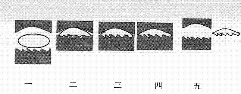
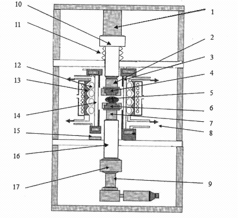
[0014] 1. See attached Figure 1~2 , The ultrasonic vibration-assisted precision compression molding device used in this embodiment is the UAPM-1 ultrasonic vibration-assisted ultra-precision compression molding machine manufactured by the Optical Instrument Factory of Hunan University, China. Select a glass blank 5 whose weight is equivalent to the weight of the target piece and introduce it into the lower mold 6 of the specified ultrasonic vibration-assisted precision molding device, open the inert gas inlet 15, and inject nitrogen gas into the lower mold 6, so as to expel the material contained in the lower mold 6. Oxygen in the molding cavity 14 inside the upper mold 4. After the molding cavity 14 reaches an oxygen-free environment, turn on the infrared lamp 12, utilize the reflection effect of the prism 13 and the partial shielding effect of the shading plate 3, and concentrate the light source to heat the lower mold 6, the upper mold 4 and the glass blank 5 by infrared r...

Embodiment 2

[0020] 1. See attached Figure 1~2 , The ultrasonic vibration-assisted precision compression molding device of this embodiment also adopts the UAPM-1 ultrasonic vibration-assisted ultra-precision compression molding machine manufactured by the Optical Instrument Factory of Hunan University in China. Select a glass blank 5 whose weight is equivalent to the weight of the target piece and introduce it into the lower mold 6 of the specified ultrasonic vibration-assisted precision molding device, open the inert gas inlet 15, and inject nitrogen gas into the lower mold 6, so as to expel the material contained in the lower mold 6. Oxygen in the molding cavity 14 inside the upper mold 4. After the molding cavity 14 reaches an oxygen-free environment, turn on the infrared lamp 12, utilize the reflection effect of the prism 13 and the partial shielding effect of the shading plate 3, and concentrate the light source to heat the lower mold 6, the upper mold 4 and the glass blank 5 by infr...


PUM


Abstract

The invention discloses an ultrasonic vibration-assisted method for precise mould pressing and shaping, comprising the following steps: 1. selecting one glass blank (5), introducing the glass blank into the lower die (6) of an ultrasonic vibration-assisted device for precise mould pressing and shaping, and irradiating by infrared ray until viscosity is 106-108dPa.s; 2. starting a servo motor (17) to drive the lower die (6) to move upwards until the glass blank (5) and an upper die (4) are compacted; 3. starting an ultrasonic vibration generator (1) to drive the upper die (4) to realize ultrasonic vibration, and then ensuring that the glass blank (5) vibrates to fill the die; 4. carrying out mould pressing again, and annealing the upper die (4) and the lower die (6); and 5. forming a finished product when the viscosity reaches 1013-1015dPa.s, moving the lower die (6) and taking out. With the method, the die with a complex molded surface can be filled, and the phenomenon of air trapping can be prevented to obtain a high-quality optical element with even structure and strength.

Description

technical field [0001] The invention relates to a molding technology, in particular to an ultrasonic vibration-assisted precision molding method for processing optical elements with complex profiles. Background technique [0002] High-performance, compact image sensing units are generally made of high-refractive index glass. Optical glass products can be molded to form optical functional surfaces. High productivity and stable mass production of optical lenses. However, for optical parts with complex profiles, especially for optical components with microstructures such as Fresnel lenses, it is difficult for the glass blank to fill the mold cavity with microstructures during the molding process, which affects the molding accuracy . At present, the widely used molding method is mostly a single lower mold or upper mold linear motion extrusion method. The optical element products produced have uneven internal structure, density, strength and stress distribution in the upper and...

Claims


Application Information

Patent Timeline
Patent Type & Authority Applications(China)
IPC IPC(8): C03B11/00
Inventor 尹韶辉朱科军陈逢军余剑武王宇唐昆
Owner HUNAN UNIV
Learn More