Laser gyro shaking stripping device

A technology of laser gyroscope and stripping, which is applied in the direction of Sagnac effect gyroscope, etc., can solve the problems such as difficult to meet the requirements and cannot be guaranteed, so as to improve the low-frequency and high-frequency response, improve the effect of jitter stripping, and improve the jitter stripping The effect of removing the effect

Inactive Publication Date: 2011-09-07
谢元平 +2
View PDF0 Cites 8 Cited by
  • Summary
  • Abstract
  • Description
  • Claims
  • Application Information

AI Technical Summary

Problems solved by technology

Since different gyroscopes have different jitter frequencies, the jitter frequency of the same gyroscope also changes with the environment and time. Therefore, when the sampling frequency fs=1/T is fixed, the digital delay of the jitter reference signals of different frequencies cannot guarantee Δα 1 , Δα 2 The phase difference between them is

Method used


Image

  • Laser gyro shaking stripping device
  • Laser gyro shaking stripping device
  • Laser gyro shaking stripping device

Examples


Example Embodiment

[0033] Hereinafter, the present invention will be further described in detail with reference to specific embodiments and the drawings of the specification.

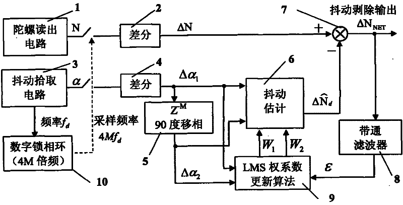
[0034] Such as figure 2 As shown, the laser gyro jitter stripping device of the present invention mainly includes a gyro readout circuit 1, a difference operation 2, a jitter pickup circuit 3, a difference operation 4, a digital delay / phase shifter 5, a jitter estimator 6, a sum operation 7, Band pass filter 8, LMS weight coefficient update algorithm 9, digital phase locked loop 10

[0035] The jitter pickup circuit 3 outputs the sinusoidal jitter reference signal α. One path of the jitter reference signal is sampled and differentiated as a reference signal for jitter stripping, and the other path is 4M multiplied by the digital phase-locked loop 10 to obtain a sampling clock synchronized with the jitter reference signal. , The sampling clock frequency is 4Mf d (M is an integer greater than or equal to 1, a preferred example...


PUM


Abstract

The invention discloses a laser gyro shaking stripping device which is used for adaptively stripping a laser gyroscope shaking signal by adopting an LMS (Least Mean Square) algorithm based on an adaptive compensation technology. The sampling frequency of the stripping device is integral multiples of shaking frequency. A sine and a cosine reference signals for stripping are obtained by using one path of sampling differential signals through simple and digital delay, system input and output response is unchangeable when approximating, and thus shaking stripping effect can be improved.

Description

technical field [0001] The invention relates to a laser gyro jitter signal stripping device, which is used for real-time elimination of jitter components in gyro output. Background technique [0002] Ring laser gyro has a series of advantages such as wide dynamic range, good linearity of scale factor, fast start-up, and insensitivity to acceleration. It is an ideal component of strapdown inertial system and is widely used in navigation, aviation, aerospace and land and other fields. [0003] There is a locking phenomenon in the laser gyro. In order to overcome the locking, it is necessary to artificially add a bias angular rate to the laser gyro, so that all or most of its working points are biased out of the locking area. The mechanical jitter bias frequency is the most commonly used bias frequency at present. technology. For the mechanically dithered frequency-biased laser gyroscope, its output signal not only contains the angular motion information of the relative inerti...

Claims


Application Information

Patent Timeline
IPC IPC(8): G01C19/66
Inventor 谢元平胡绍民龙兴武
Owner 谢元平
Why Eureka
Try Eureka