Double-end double-wavelength self-compensation distributed optical fiber temperature sensor

A distributed optical fiber, temperature sensor technology, applied in thermometers, thermometers with physical/chemical changes, instruments, etc., can solve the problems of inability to obtain the accurate cutting information of the sensing fiber at the same time, measurement inaccuracy, etc., to improve Raman The effect of scattered light intensity, improving temperature measurement accuracy, and increasing signal-to-noise ratio

Inactive Publication Date: 2011-09-07
SHANGHAI BOOM FIBER SENSING TECH
View PDF8 Cites 9 Cited by
  • Summary
  • Abstract
  • Description
  • Claims
  • Application Information

AI Technical Summary

Problems solved by technology

[0005] However, since the optical path switcher can only be connected to one end of the sensing fiber at a time, the system

Method used


Image

  • Double-end double-wavelength self-compensation distributed optical fiber temperature sensor
  • Double-end double-wavelength self-compensation distributed optical fiber temperature sensor
  • Double-end double-wavelength self-compensation distributed optical fiber temperature sensor

Examples


Embodiment 1

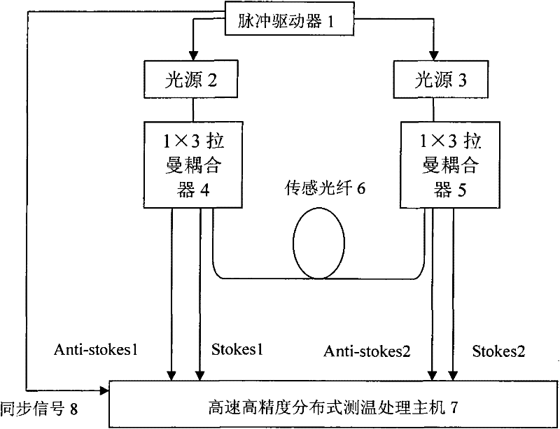
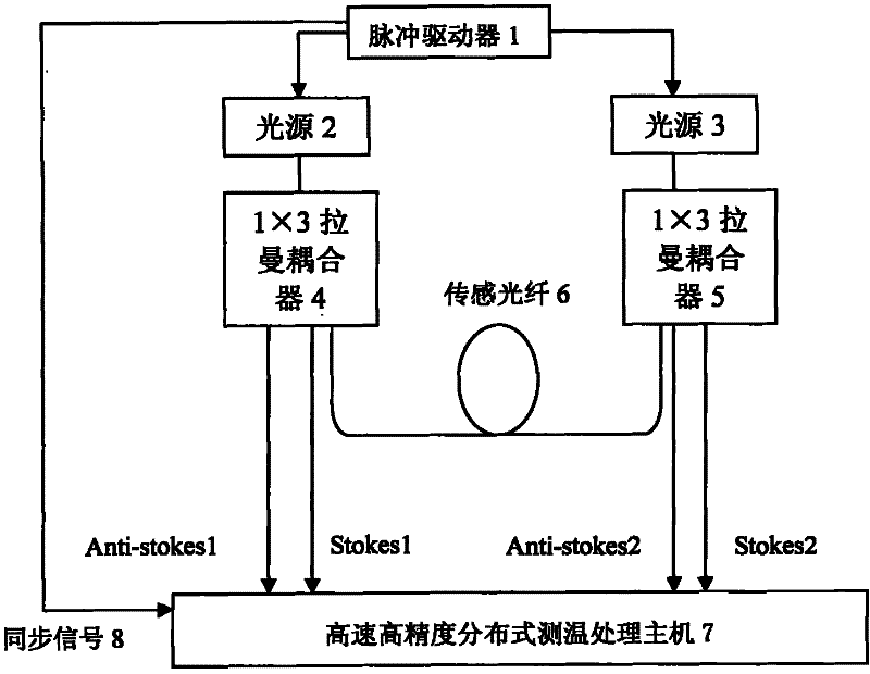
[0015] Embodiment 1: as figure 1 As shown, the pulse driver 1 is connected to two light sources 2 and 3, the light sources 2 and 3 are respectively connected to 1×3 Raman couplers 4 and 5, and the output ends of the two 1×3 Raman couplers are respectively connected to the sensing fiber 6 One end and the other two output ends are connected to a high-speed, high-precision distributed temperature measurement and processing host 7 through optical fibers.

[0016] The light source 2 and the light source 3 emit two pulsed lights with different wavelengths under the action of the pulse driver 1, and the two beams of pulsed light are injected into the two ends of the sensing fiber 6 through two 1×3 Raman couplers. Backward Raman scattering occurs during transmission in the optical fiber, and the obtained backward Raman scattered light returns from both ends of the sensing fiber to the 1×3 Raman coupler, because the 1×3 Raman coupler itself has the function of filtering light , so in ...

Embodiment 2

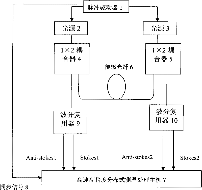
[0018] Embodiment 2: as figure 2 As shown, the pulse driver 1 is connected to two light sources 2 and 3, and the light sources 2 and 3 are respectively connected to 1×2 couplers 4 and 5, and one output end of the two 1×2 couplers is respectively connected to one end of the sensing fiber 6, and the other One output end is respectively connected to a wavelength division multiplexer 9 and 10, and the two wavelength division multiplexers are connected to a high-speed and high-precision distributed temperature measurement and processing host 5 through an optical fiber.

[0019] The light source 2 and the light source 3 emit two kinds of pulsed light with different wavelengths under the action of the pulse driver 1, and the two beams of pulsed light are injected into the two ends of the sensing fiber 6 through two 1×2 couplers, and the pulsed light is in the sensing fiber Back Raman scattering occurs during transmission, and the obtained back Raman scattered light returns to two 1×...


PUM


Abstract

The invention relates to a double-end double-wavelength self-compensation distributed optical fiber temperature sensor, in which two light sources are controlled by a pulse driver to emit pulse light of two wavelengths, and two groups of back Raman scattering light with different wavelengths are obtained at a tail end of a sensing optical fiber. The structure of the sensor is a double-wavelength light self-compensation structure, for the same optical fiber section under temperature function, output results of two back-scattering light wavelength paths are obtained, and the results are compared, so that a reference comparison system is built in the system, change of inner chromatic dispersion and spectrum loss of the sensing optical fiber and instability factors are eliminated, the system has better stability and accuracy, and the aim of improving the system performance is implemented.

Description

technical field [0001] The invention relates to the technical field of optical fiber sensing, in particular to the technical field of dual-terminal dual-wavelength self-compensating distributed optical fiber temperature sensing. Background technique [0002] The concept of fiber optic sensors is not new, as early as the mid-1960s, the first patents appeared, which include Fotonic mechanical displacement sensors using beam transmission and ultrasonic sensors using phase modulation. However, in a broader field, that is, optical fiber sensing technology, it was only 10 years later that a series of research was achieved. Since then, optical fiber technology has broken through the stagnant state and entered an era of rapid progress. [0003] Since the advent of the distributed optical fiber temperature sensor, many commercial products have appeared so far, and have achieved significant economic and social benefits. Since the distributed optical fiber temperature sensor needs to d...

Claims


Application Information

Patent Timeline
IPC IPC(8): G01K11/32G01K11/324
Inventor 杨斌皋魏席刚仝芳轩周正仙
Owner SHANGHAI BOOM FIBER SENSING TECH
Why Eureka
Try Eureka