Drying system used in airplane

A drying system and aircraft technology, applied in aircraft parts, air treatment equipment, gas treatment, etc., can solve the problems of increasing aircraft power consumption, increasing aircraft equipment weight, increasing aircraft energy consumption, etc., to reduce fuselage corrosion, Reduces electrical failures and short circuits, and eliminates the effect of condensation or ice accumulation

Active Publication Date: 2013-05-01
COMAC +1
View PDF4 Cites 0 Cited by
  • Summary
  • Abstract
  • Description
  • Claims
  • Application Information

AI Technical Summary

Problems solved by technology

In the prior art, some aircraft control the generation of condensed water by adding a drying system, but most of them are special drying systems to dehumidify and heat the air in the cabin, which will lead to an increase in the weight of the aircraft equipment, and at the same time It will increase the power consumption of the aircraft, which will lead to an increase in the energy consumption of the aircraft, that is, this dehumidification method is based on the increase in energy consumption of the aircraft

Method used


Image

  • Drying system used in airplane
  • Drying system used in airplane

Examples


Embodiment Construction

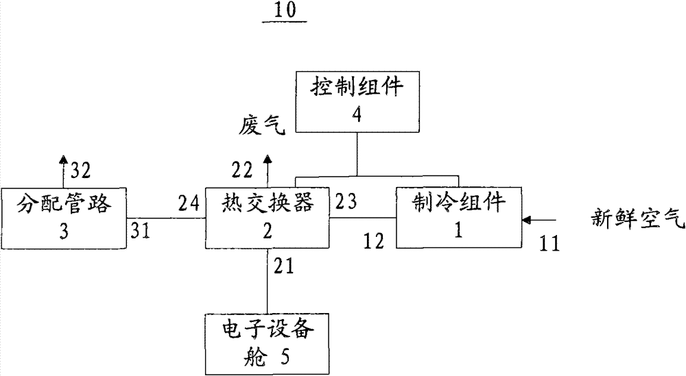
[0014] Such as figure 1 As shown, it shows a schematic diagram of the drying system of the present invention, wherein the drying system 10 is composed of a refrigeration assembly 1 , a heat exchanger 2 , a distribution pipeline 3 and a control assembly 4 . The refrigerating assembly 1 has an air inlet port 11 for the first dehumidification and an air outlet port 12 for the first dehumidification, which are used for performing the first dehumidification of the fresh air entering from the air inlet port 11 for the first dehumidification. Dehumidification thereby reducing its absolute humidity. The heat exchanger 2 has an exhaust gas inlet port 21 , an exhaust gas outlet port 22 , an air inlet port 23 for the second dehumidification, and an air outlet port 24 for the second dehumidification. Wherein, the waste gas inlet port 21 communicates with the electronic equipment compartment 5, the waste gas discharge port 22 communicates with the outside of the aircraft, and the second d...


PUM


Abstract

Disclosed is a dehumidification system for use in an airplane, comprising: a cooling assembly (1) having an air inlet port (11) for a first round of dehumidification and an air outlet port (12) for the first round of dehumidification, when the cooling assembly (1) conducts the first round of dehumidification on the fresh air entering from the air inlet port (11) for the first round of dehumidification so as to reduce the absolute humidity thereof; a heat exchanger (2) having a waste gas inlet port (21), a waste gas outlet port (22), an air inlet port (23) for a second round of dehumidification and an air outlet port (24) for the second round of dehumidification, with the waste gas inlet port (21) being in communication with an electronics bay (5), the heat exchanger (2) being used for conducting a heat exchange on the hot waste gas discharged from the electronics bay (5) and the cold fresh air discharged from the cooling assembly (1) so as to perform a second round of dehumidification for the reduction of the relative humidity thereof to obtain dehumidified air; a distribution pipeline (3) for transporting the dehumidified air into an interlayer of the fuselage; and a control assembly (4).

Description

technical field [0001] The invention relates to a drying system for use in aircraft. More specifically, the present invention relates to a drying system for use in aircraft that reduces energy consumption. Background technique [0002] During the flight of the aircraft, each passenger exhales about 100 grams of water vapor per hour, and these water vapors will cool down rapidly after encountering the cold mechanism of the aircraft to form condensed water. Therefore, the amount of condensed water formed during a long-term flight is very amazing. As a result, after the condensed water is absorbed by the heat insulation layer and other equipment in the fuselage, the weight of the aircraft will increase by more than half a ton (the amount of condensed water is mainly related to the number of passengers, the mode of operation of the aircraft, and the regional climate), and the increased weight will lead to Higher fuel consumption and negative impact on the environment. To make...

Claims


Application Information

Patent Timeline
Patent Type & Authority Patents(China)
IPC IPC(8): B01D53/26B64D13/00
CPCB01D2259/4575B64D2013/0662B64D13/00Y02T50/56B01D53/265Y02T50/50
Inventor 孙学德南国鹏辛旭东
Owner COMAC
Why Eureka
Try Eureka