

Assembly welding method of chassis assembly and assembly welding tooling clamping devices special for same
A clamping device and welding tooling technology, applied in auxiliary devices, manufacturing tools, welding equipment and other directions, can solve the problems of long processing period, high processing cost, deformation of the car body, etc., and achieve the effect of improving work efficiency and saving costs.
- Summary
- Abstract
- Description
- Claims
- Application Information
AI Technical Summary
Problems solved by technology
Method used
Image

Examples
Embodiment 1
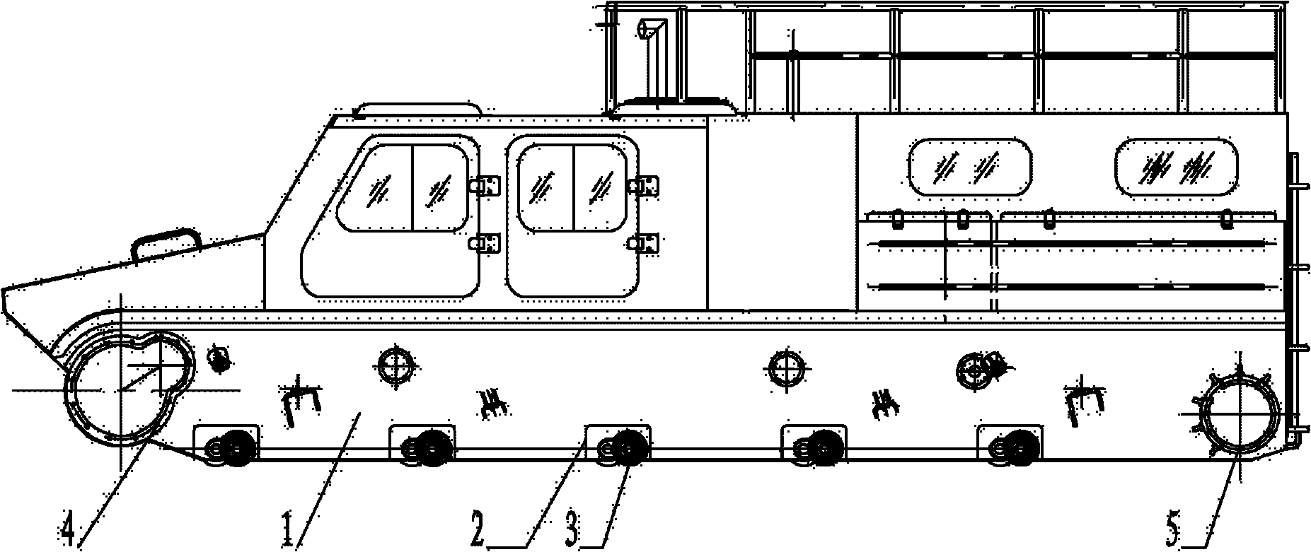
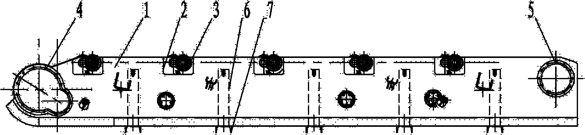
[0016] Embodiment 1, the specific process steps of the present invention are as follows: the first step, cut out each bridge hole 2 on the left and right side decks 1 according to the design requirements, preferably adopt the water cutting method to process each bridge hole to the final size of the drawing design; The axle flange, the rear axle flange and the gearbox bracket are respectively processed in place on the small machine tool according to the drawings, and no machining allowance is reserved, that is, they are processed to the standard size during assembly, and then the side deck side beams 11 and 11 are welded. Other attachments required by the design, and a through hole for positioning is provided on the side deck side beam 11. This through hole should be matched with the positioning hole designed on the clamping device of the welding tool. At this time, the side deck 1 is completed. preliminary processing. In the second step, the left and right side decks 1 are tur...
Embodiment 2
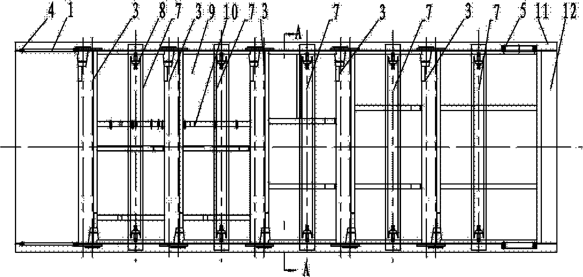
[0020]Embodiment 2, the present invention can adopt a kind of special-purpose assembly welding fixture clamping device, and it comprises bottom beam 7, column 6 and upper beam 13 to form clamping support, and column 6 is affixed symmetrically respectively on both sides of bottom beam 7 top, The upper beam 13 is affixed between the two columns 6, and the support rod 15 can also be affixed between the column 6 and the upper beam 13. Positioning screw holes 20 for installing the installation device are respectively provided at both ends of the bottom beam 7, and through holes for installing the adjustment device are provided on the upper parts of the two uprights 6, and the side deck state adjustment mechanism 8 is set in the through holes on the upper parts of the uprights 6. , the side deck state adjustment mechanism 8 includes a screw hole and a side plate adjusting screw 19 that are fixedly connected with the through hole on the upper part of the column 6, and the side plate a...
Embodiment 3
[0021] Embodiment 3, the side deck state adjustment mechanism 8 of the present invention can also adopt another kind of structural form, and it can be connected by the screw hole that cooperates with the through hole on the upper part of the column 6, the connecting block bracket 16, the bolt 17, and the positioning connection. Block 18 and side plate adjusting screw rod 19 etc. are formed, and side plate adjusting screw rod 19 is sleeved in the screw hole, and the front end of side plate adjusting screw rod 19 is sleeved connecting block bracket 16, and connecting block bracket 16 and positioning connecting block 18 are provided with pin holes , the bolt 17 passes through the bolt hole on the connecting block bracket 16 and the positioning connecting block 18 to set the positioning connecting block 18 in the connecting block bracket 16, and at this moment, the positioning connecting block 18 can be replaced as required. refer to Figures 1 to 6 , the rest of Example 2.
PUM
 Abstract
Description
Claims
Application Information