Valve stroke testing system

A testing system and valve stroke technology, applied in valve devices, measuring devices, instruments, etc., can solve the problems of expensive valves, wear of sealing surfaces, internal leakage of valves, etc., to achieve accurate and reliable test results, avoid adverse effects, and avoid valve damage effect

Active Publication Date: 2011-09-14
HEFEI GENERAL MACHINERY RES INST +1
View PDF5 Cites 41 Cited by
  • Summary
  • Abstract
  • Description
  • Claims
  • Application Information

AI Technical Summary

Problems solved by technology

[0006] 1. The full stroke test is to perform one or several complete "open" or "close" actions on the valve when the process is interrupted or the valve under test is bypassed. This "offline" test requirement greatly limits Testing of valves working under in-service conditions in the field;
[0007] 2. During the full-stroke test, the rapid switching process will inevitably lead to multiple instantaneous huge impacts between the valve core and the contact surface. This impact is an important factor that causes sealing surface wear, valve internal leakage, and valve stem bending deformation;
This type of valve with an intelligent positioner is expensive and is usually only used as a control valve, but is rarely used in important valves such as on-off valves, interlock valves or shut-off valves. Therefore, a large number of switches without intelligent positioners are installed in actual production. Valves, interlock valves or shut-off valves cannot be tested online
[0011] 2. The online test method is to draw a curve of the corresponding relationship between the force of the tested valve and the stroke of the valve stem, and compare the curve with the new valve to evaluate the action performance of the tested valve. Valves, whose corresponding new valve performance curves are not available, also make this kind of online testing impossible

Method used


Image

  • Valve stroke testing system
  • Valve stroke testing system
  • Valve stroke testing system

Examples


Embodiment Construction

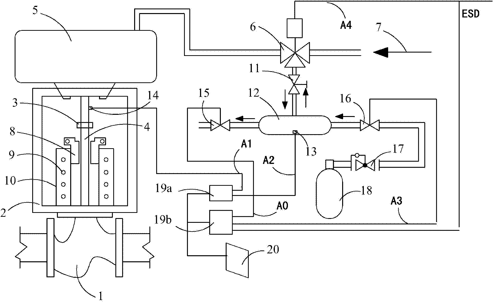
[0051] see figure 1 , the system configuration in this embodiment includes a measured valve, an intake and exhaust device, and a detection unit;

[0052] The structural setting of the tested valve includes: controlling the instrument air 7 to enter the air intake into the pneumatic actuator 5 through the two-position three-way solenoid valve 6, or controlling the exhaust of the pneumatic actuator 5 to drive the pneumatic actuator 5; A sensing unit 14 for relevant information of the valve stem 4, the sensing unit 14 includes a speed sensor for detecting the movement speed of the valve stem, an acceleration sensor for detecting the movement acceleration of the valve stem, and a displacement sensor for detecting the displacement of the valve stem;

[0053] The structural setting of the intake and exhaust device includes: one way of the buffer tank 12 is connected with the external instrument air tank 18 through the intake solenoid valve 16 and the pressure reducing valve 17 in t...


PUM


Abstract

The invention discloses a valve stroke testing system which is characterized in that the system comprises a tested valve, a valve rod stroke control mechanism, an air intake and exhaust control device and a detecting unit; the tested valve comprises a pneumatic actuating mechanism and a sensor unit, wherein the pneumatic actuating mechanism controls the air intake or air exhaust through a two-position three-way electromagnetic valve; the sensor unit is used for obtaining the related information of a valve rod; the valve rod stroke control mechanism is provided with a limit sleeve; the valve rod is provided with a limit stop which is used for limiting a part of stroke of the valve rod; the air intake and exhaust control device is communicated with a circumscribed instrument air tank through an air intake electromagnetic valve according to one way of a buffer tank; the other way of the air intake electromagnetic valve is communicated with an air exhaust electromagnetic valve; one way of the air intake electromagnetic valve is communicated with the two-position three-way electromagnetic valve through a manual valve; and the detecting unit is used for collecting detecting signals and providing control signals of the two-position three-way electromagnetic valve, the air exhaust electromagnetic valve and the air intake electromagnetic valve. the valve stroke testing system provided by the invention can be used for online or off-line test of the valve stroke, can be used for full stroke or partial stroke test for the valve, and can be applied to pneumatic-type interlocked valves without mounting intelligent positioning devices in all industries.

Description

technical field [0001] The present invention relates to a valve testing system, more specifically a pneumatic interlocking valve which is suitable for process industries (petroleum, chemical industry, metallurgy, electric power and other industries) and uses compressed gas as the power to realize the off-line or on-line switching performance of the valve. Test system and test method. The present invention can be used for on-line or off-line detection of in-service valves to obtain the resistance encountered during the valve switch process and the corresponding relationship between the resistance and the stroke, so as to evaluate the performance of the above-mentioned valve performing the switching action. The test method of the present invention is also applicable to hydraulic interlock valves powered by hydraulic oil. Background technique [0002] Pneumatic interlock valves powered by compressed air are widely used in petroleum, chemical, metallurgy, electric power and oth...

Claims


Application Information

Patent Timeline
Patent Type & Authority Applications(China)
IPC IPC(8): F16K37/00G01B21/02
Inventor 朱建新陈学东于改革关卫和艾志斌杨铁成方向荣庄力健袁文彬
Owner HEFEI GENERAL MACHINERY RES INST
Why Eureka
Try Eureka